Business form comprising a wristband with multiple imaging areas
What is AI technical title?
AI technical title is built by Patsnap AI team. It summarizes the technical point description of the patent document.
a wristband and imaging area technology, applied in the field of business forms comprising wristbands with multiple imaging areas, can solve the problems of limited imagination of designers, limited use of auxiliary imaging areas, and practicable limitations to this length, and achieve the effect of long imaging area
Inactive Publication Date: 2010-07-27
ZEBRA TECH CORP
View PDF164 Cites 47 Cited by
Summary
Abstract
Description
Claims
Application Information
AI Technical Summary
This helps you quickly interpret patents by identifying the three key elements:
Problems solved by technology
Method used
Benefits of technology
Benefits of technology
[0002]Although this desire to provide maximum “real estate” for imaging leads to longer imaging areas, the anatomical limits of the patient's wrist around which the wristband wraps create some practical limitations to this length, even for adult sized wristbands. As the imaging area is typically made from a face stock or other print receptive material such as bond paper, it typically exhibits a relative stiffness when compared with the laminate backing ply. This relative stiffness helps the imaging area to lie flat against the wrist so as to enhance the readability of the data imaged onto it. However, as the imaging area is typically a single length of regularly sized face stock, formed into the shape of a rectangle with rounded corners, the imaging area can have a tendency to bow, or assume an arcuate shape, to more closely fit about the patient's wrist especially if the wristband is tightened close to the wrist. While this does present some inconvenience for a nurse or other medical professional seeking to read the information contained in the imaging area, it is more of a problem now that bar codes have come into common usage. That's because bar code readers are better able to accurately read when the bar code is lying flat and not on a curved surface.
Problems solved by technology
Although this desire to provide maximum “real estate” for imaging leads to longer imaging areas, the anatomical limits of the patient's wrist around which the wristband wraps create some practical limitations to this length, even for adult sized wristbands.
While this does present some inconvenience for a nurse or other medical professional seeking to read the information contained in the imaging area, it is more of a problem now that bar codes have come into common usage.
There are other uses for the auxiliary imaging area, limited only by the imagination of the designer.
Method used
Image
Click on the blue label to locate the original text in one second.
Reading with bidirectional positioning of images and text.
Examples
Embodiment Construction
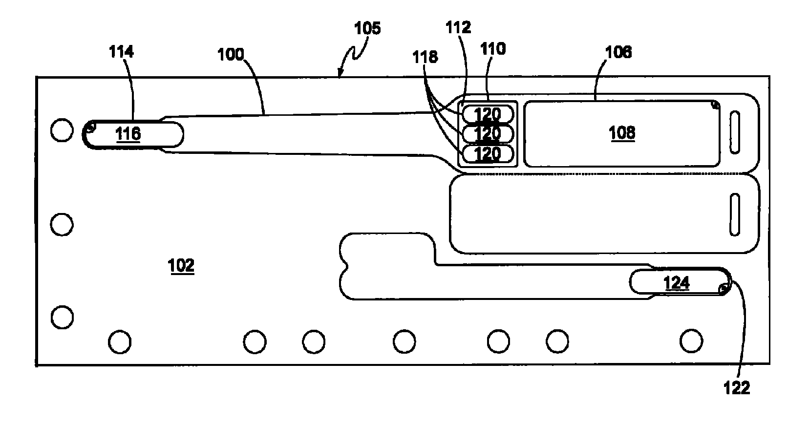
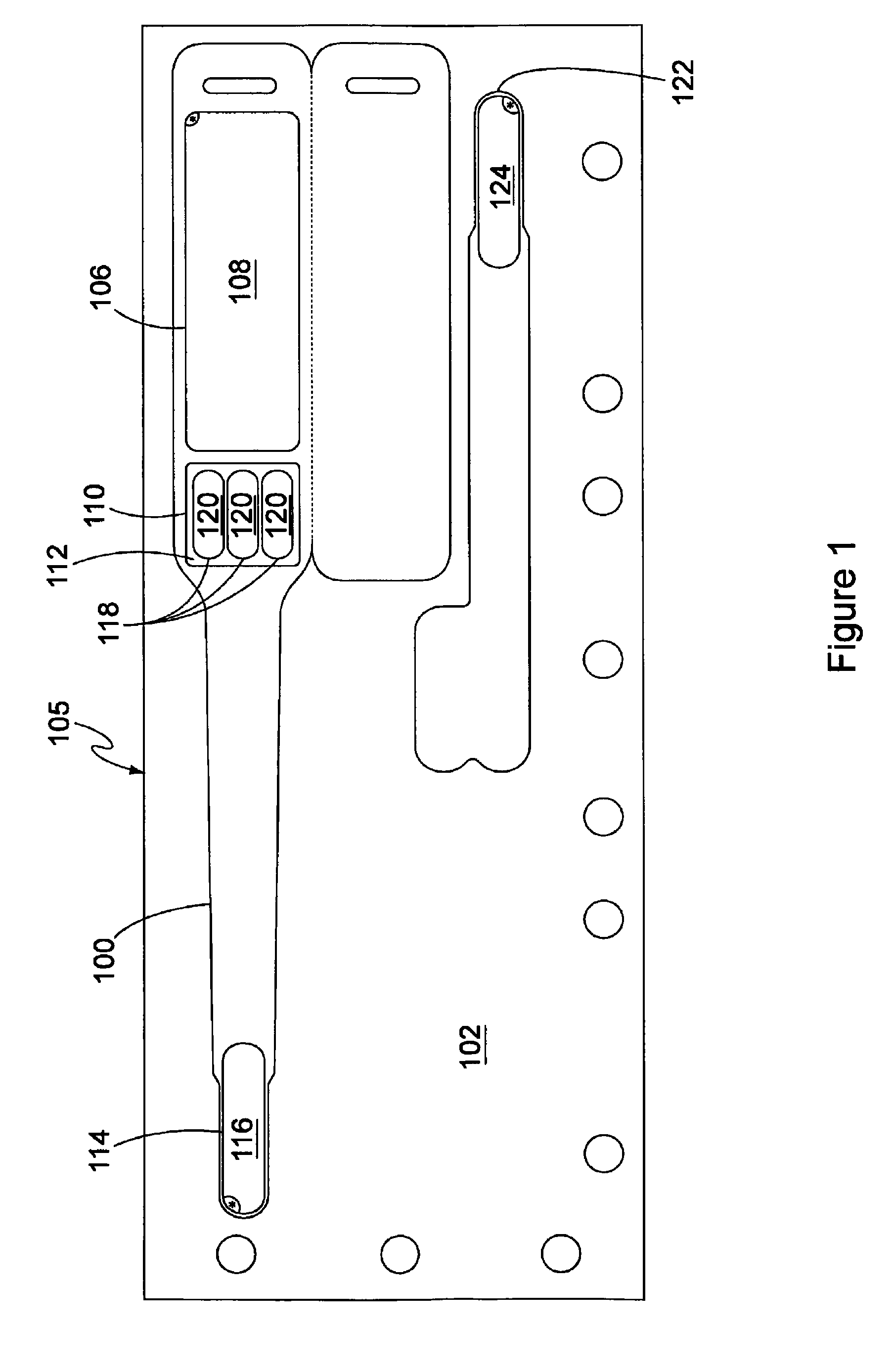
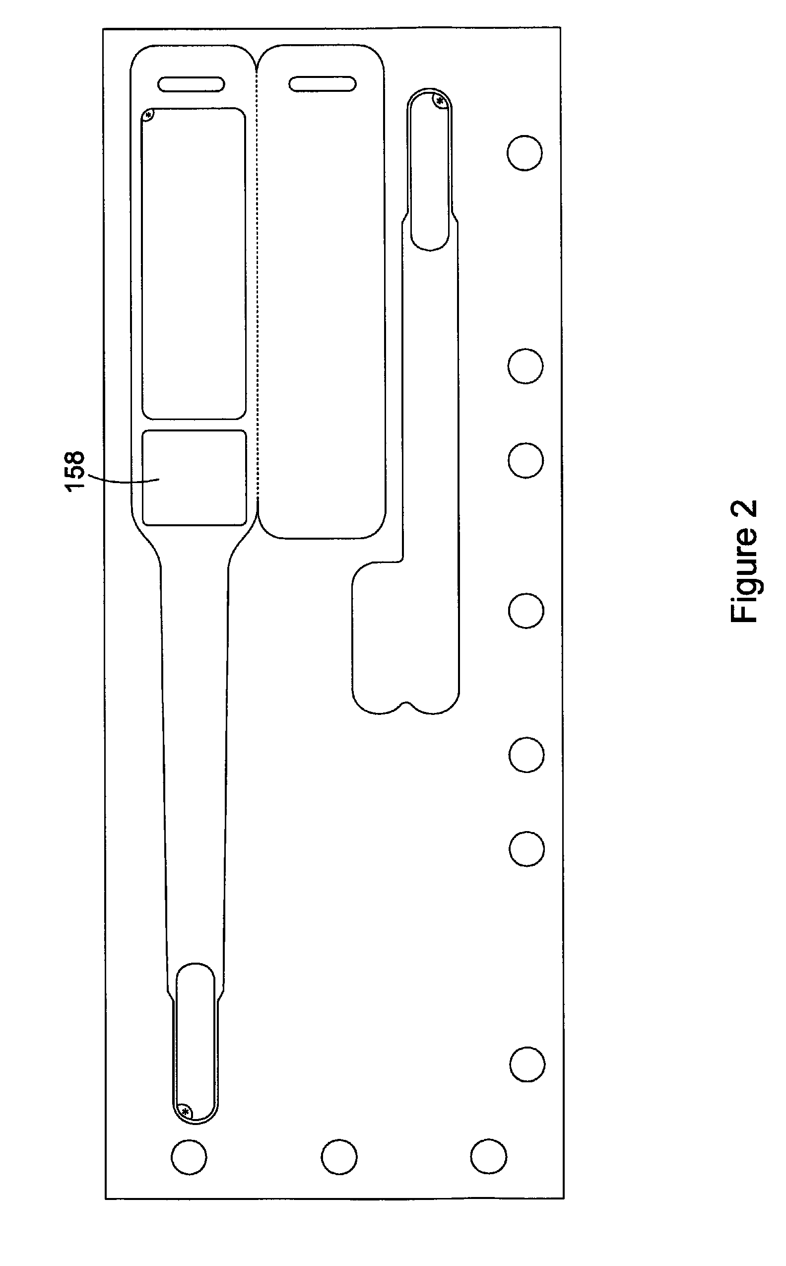
[0020]The wristband 100 of the present invention is shown as a first embodiment in FIGS. 1, 4 as defined by a plurality of die cuts in the face ply layer 102 of FIG. 1 and the laminate ply layer 104 of FIG. 4, both of which comprise a sheetlet sized page 105. As shown in FIG. 1, a first die cut 106 defines a first imaging area 108, a second die cut 110 defines a second side car or auxiliary imaging area 112 and a third die cut 114 defines a removable tab 116 covering of a layer of adhesive for use in securing the wristband as will be explained below. Also as shown in FIG. 1, three separate print lines 118 define three separate ellipse target areas 120 for adhering the special precautions markers described below. These special precautions markers are preferably of different color to indicate a different condition, such as allergies, fall risk, do not resuscitate, etc. Also shown in FIG. 1 is a die cut 122 which defines a removable tab 124 covering of a layer of adhesive for use in se...
PUM
Property
Measurement
Unit
size
aaaaa
aaaaa
area
aaaaa
aaaaa
length
aaaaa
aaaaa
Abstract
A self laminating wristband separable from a multi-ply page form has a plurality of separated imaging areas, with one larger imaging area for receiving printed data corresponding to the wearer such as his name, i.d. number, etc., with one or more second imaging areas adapted to receive either printed information or markers which may be adhered thereto. The separated imaging areas are aligned along the length of the wristband so that the gap between them acts as a natural hinge point which allows the imaging areas to lie flatter against the wearer's wrist.
Description
BACKGROUND AND SUMMARY OF THE INVENTION[0001]Wristbands formed by die cuts made in multi-ply forms so as to be processible by printers and especially laser printers are known in the art. One of the inventors herein is an inventor of a number of different wristband forms as shown in his prior U.S. Pat. Nos. 5,933,993, 6,000,160, 6,067,739, 6,438,881, 6,510,634, 6,748,687, 7,017,293 and 7,017,294, the disclosures of which are incorporated herein by reference. Each of the wristbands disclosed in these prior patents are self laminating, meaning that they contain a laminate layer or ply which, when the wristband is separated from its carrier, may be folded over to encapsulate an imaging area typically defined by a die cut in a face stock ply. These imaging areas are desirably sized to extend along a substantial length thereof so as to provide “real estate” for receiving printed data. This printed data may include the patient's name, the attending doctor's name, a patient ID number, admis...
Claims
Application Information
Patent Timeline
Application Date:The date an application was filed.
Publication Date:The date a patent or application was officially published.
First Publication Date:The earliest publication date of a patent with the same application number.
Issue Date:Publication date of the patent grant document.
PCT Entry Date:The Entry date of PCT National Phase.
Estimated Expiry Date:The statutory expiry date of a patent right according to the Patent Law, and it is the longest term of protection that the patent right can achieve without the termination of the patent right due to other reasons(Term extension factor has been taken into account ).
Invalid Date:Actual expiry date is based on effective date or publication date of legal transaction data of invalid patent.

