

Plug-flow regeneration process
a regeneration process and plug-flow technology, applied in specific water treatment objectives, water/sludge/sewage treatment, magnetic materials, etc., can solve the problems of unacceptably high levels of dispersed or suspended organic compounds and materials, water supplies, and particular difficulties, so as to achieve the effect of less waste and regenerating a larger quantity of resin
- Summary
- Abstract
- Description
- Claims
- Application Information
AI Technical Summary
Benefits of technology
Problems solved by technology
Method used
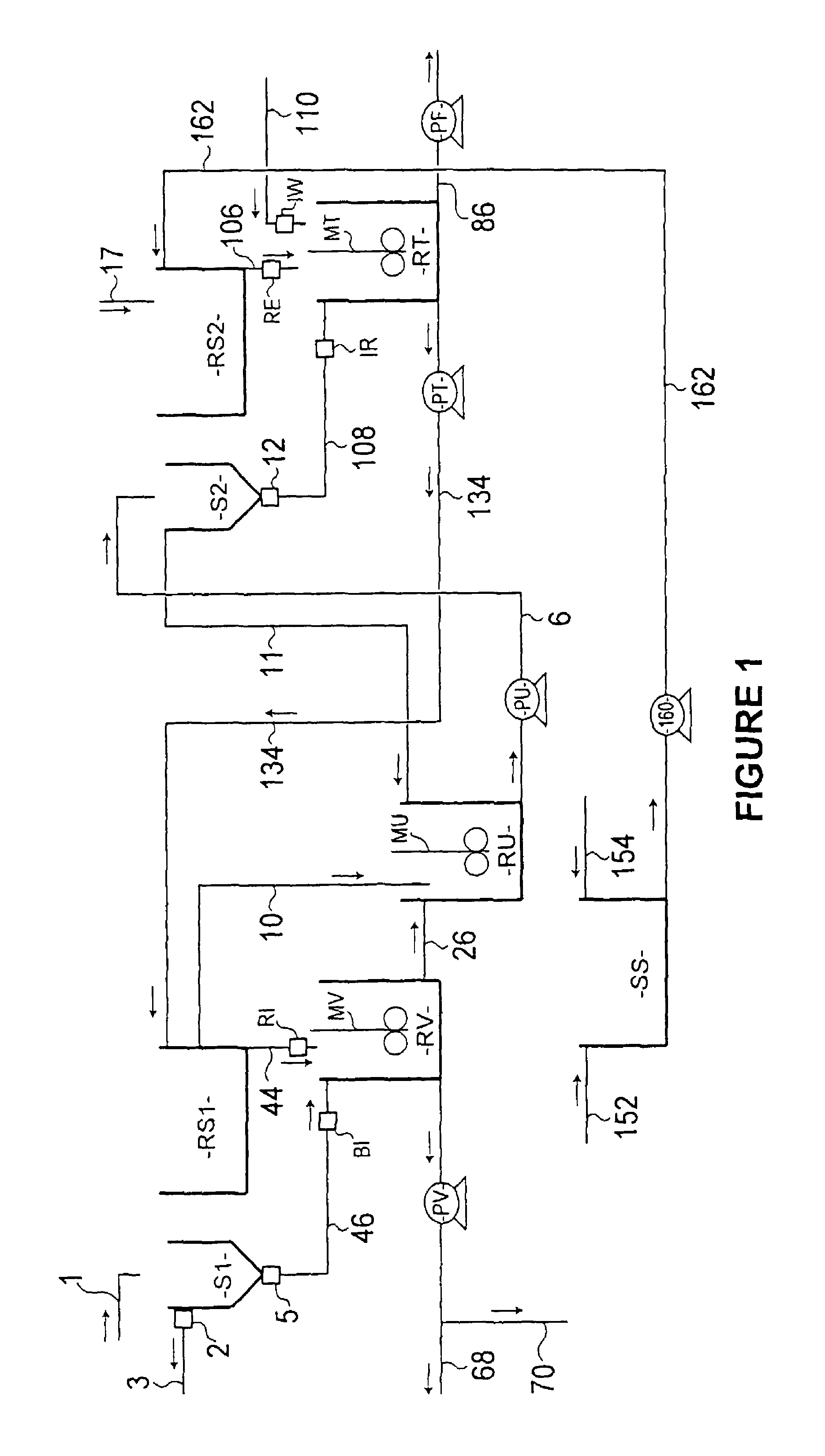
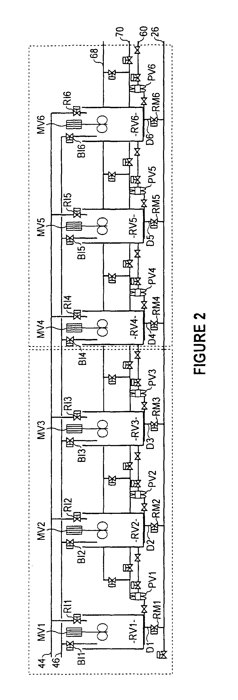
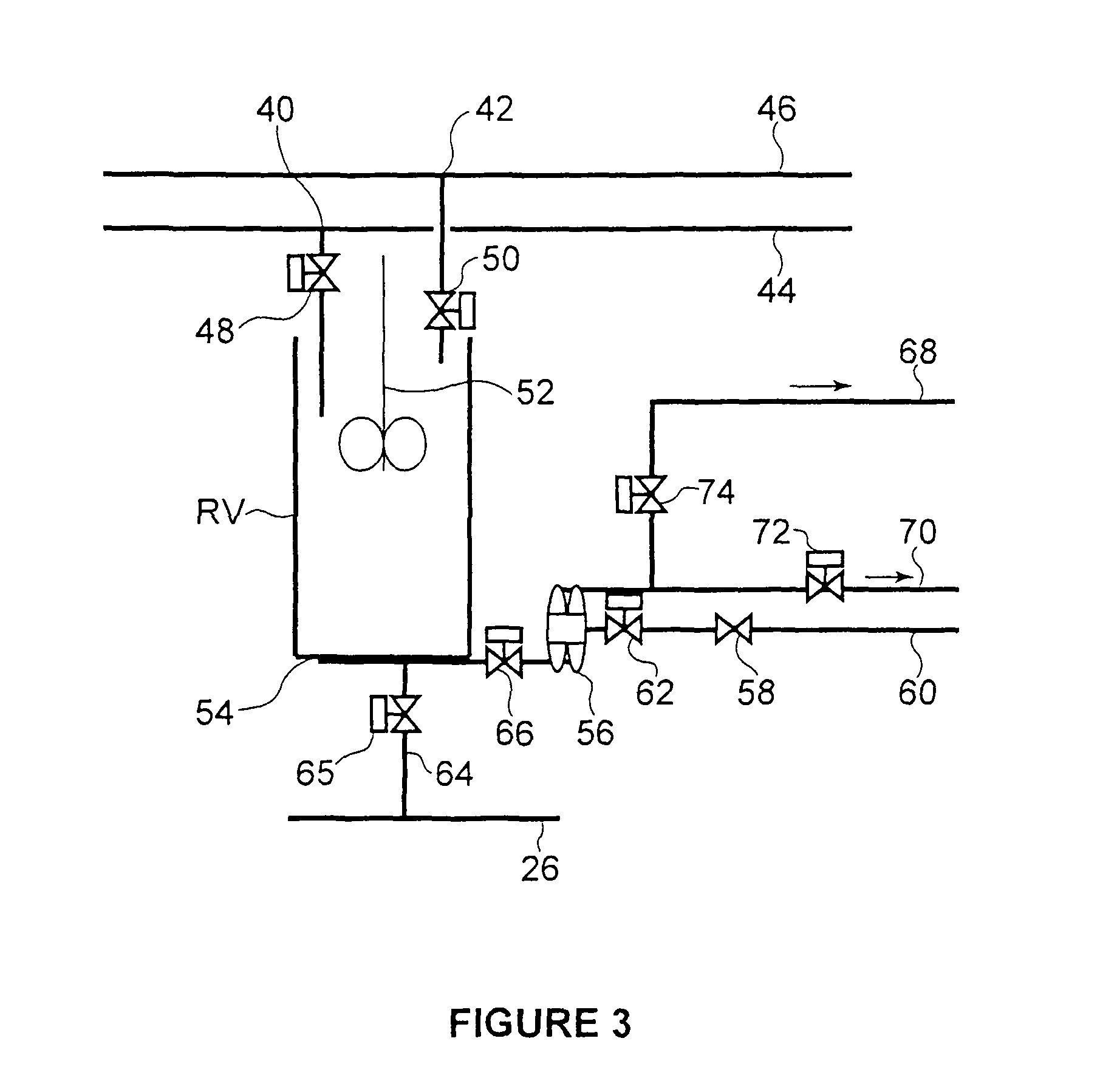
Image

Examples
example 1
Modular Package
[0235]A modular package incorporating the equipment necessary to self-install a regeneration system according to the present invention includes components for the set up of the first and third regeneration stages (regeneration modules) and an optional soaking storage tank (soaking module).
[0236]The components which make up each of the first and third regeneration stage modules include six regeneration vessels. Suitable vessels include for instance those supplied by Nylex having a volume of 2.25 m2, length of 1800 mm and height of 1900 mm. Other components include 6 regeneration mixers. Suitable mixers are low shear impeller mixers such as those supplied under model type Mixtec HA715 or Lightnin A310. Additional components for the first and second regeneration stages include 2 conductivity meters, for example those supplied under the model type Yokogawa Electrodeless-toroidal (0 to 200 mS / cm), one pressure regulator, 20 George Fisher actuated valves, 20 George Fisher m...
example 2
Regeneration Trial Process
[0240]Resin was regenerated using two tall, cylindrical regeneration columns (210) and (212) and one agitated mixing tank (214) as shown in FIG. 9. The regeneration process is described. The procedure was completed initially to obtain conductivity curves against bed volume of regenerant and rinse water pulled through the columns (210) and (212). These curves are depicted in the graphs designated FIGS. 10 to 16 and were used to determine the initial operating procedures described below. Once the procedure and operating parameters were decided, operation commenced and the conductivity and UV were measured for the first and fourth regeneration. Once these curves were obtained (FIGS. 10 to 16) the method was modified and samples were once again taken.
a) Initial Procedure
[0241]The resin to be regenerated is allowed to build up in column 210 over a four-hour period, aiming for 2100 ml of settled resin each four-hour period. This is just above the 300 mm level in ...
example
Osmotic Shock Analysis
[0306]The use of highly concentrated or saturated brine solutions to regeneration ion-exchange resin is not recommended due to the physical damage that can be done to the resin by osmotic shock, which causes expansion, contraction or disintegration of the resin.
[0307]A 12% brine solution has been successfully used to regenerate MIEX® resin, when in service in water treatment plants. This concentration has been found to be safe, as it did not cause osmotic shock to the resin beads. However, replenishment of resin is still required on these plants due to losses by chemical and physical attrition and by losing intact beads over the settler.
[0308]A trial was conducted to determine if use of saturated brine in place of a 12% solution of brine would have any impact on resin strength or DOC removal efficacy. It was expected that the higher concentration of brine may cause the resin physical damage through osmotic shock. Surprisingly, no adverse affects on the resin we...
PUM
| Property | Measurement | Unit |
|---|---|---|
| sizes | aaaaa | aaaaa |
| sizes | aaaaa | aaaaa |
| sizes | aaaaa | aaaaa |
Abstract
Description
Claims
Application Information