Magnetic field generator

a generator and magnetic field technology, applied in the direction of magnetic bodies, superconducting magnets/coils, superconductor devices, etc., can solve the problems of inability to make a distance between the upper and lower superconducting magnets, high price and difficulty in handling

Inactive Publication Date: 2010-07-27
HITACHI LTD
View PDF28 Cites 7 Cited by
  • Summary
  • Abstract
  • Description
  • Claims
  • Application Information

AI Technical Summary

Benefits of technology

[0012]With the magnetic field generator according to the invention, it is possible to present an intense magnetic field in a position of use and further to maintain a superconductive state over a long term even when a refrigerator stops due to power failure, etc.

Problems solved by technology

Further, the high-temperature superconducting material has an advantage that it is unnecessary to use a liquid helium, which is expensive and difficult to handle.
Accordingly, it is not possible to make a distance between the upper and lower superconducting magnets smaller than a predetermined dimension.

Method used


Image

  • Magnetic field generator
  • Magnetic field generator
  • Magnetic field generator

Examples


first embodiment

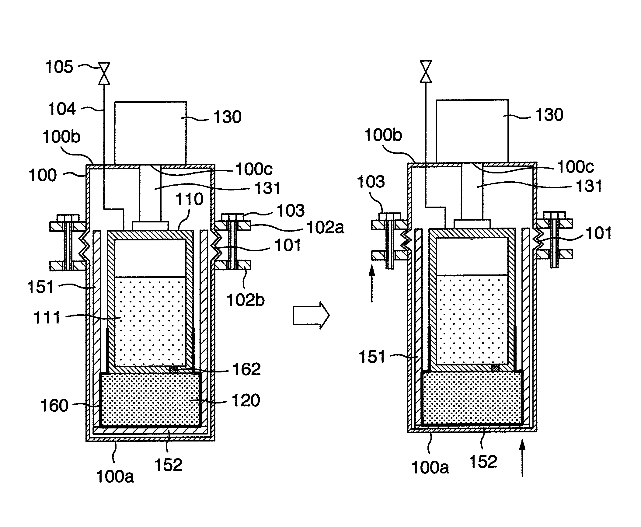
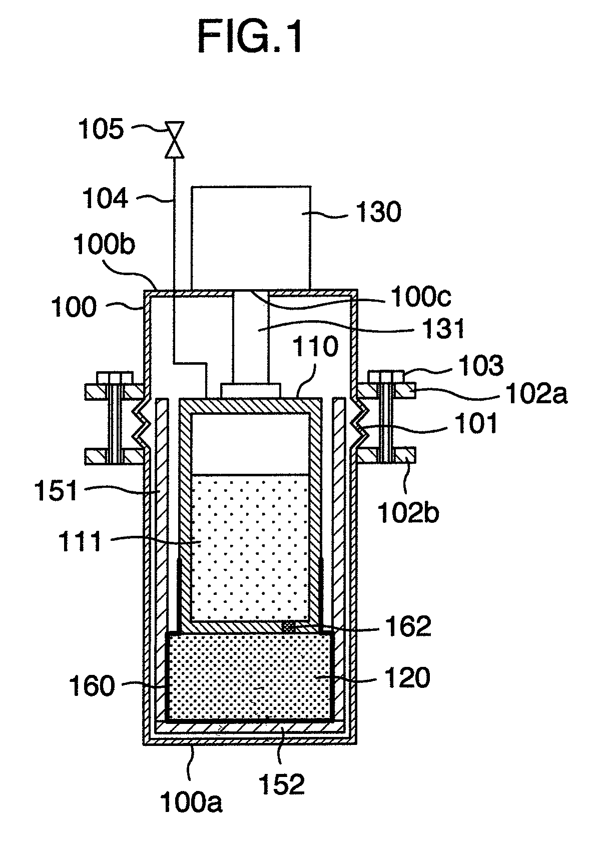
[0022]a magnetic field generator according to the invention will be described with reference to FIG. 1. The magnetic field generator according to the present embodiment is one for magnetic induction type DDS (Drug Delivery System). With the magnetic induction type DDS, an agent (called a magnetic agent) added to magnetic fine grains is injected into a patient's body. A magnetic force is made use of to guide a magnetic agent to an affected part, thereby increasing the concentration of the agent in the affected part. Thus it is possible to increase the concentration of the agent in the affected part without increasing an amount of the agent being injected into a patient's body.

[0023]A magnetic induction type DDS needs a high magnetic field for guiding a magnetic agent in a patient's body, or a magnetic field generator for generation of a high magnetic gradient.

[0024]The magnetic field generator according to the embodiment includes a vacuum container 100, an interior of which is evacua...

second embodiment

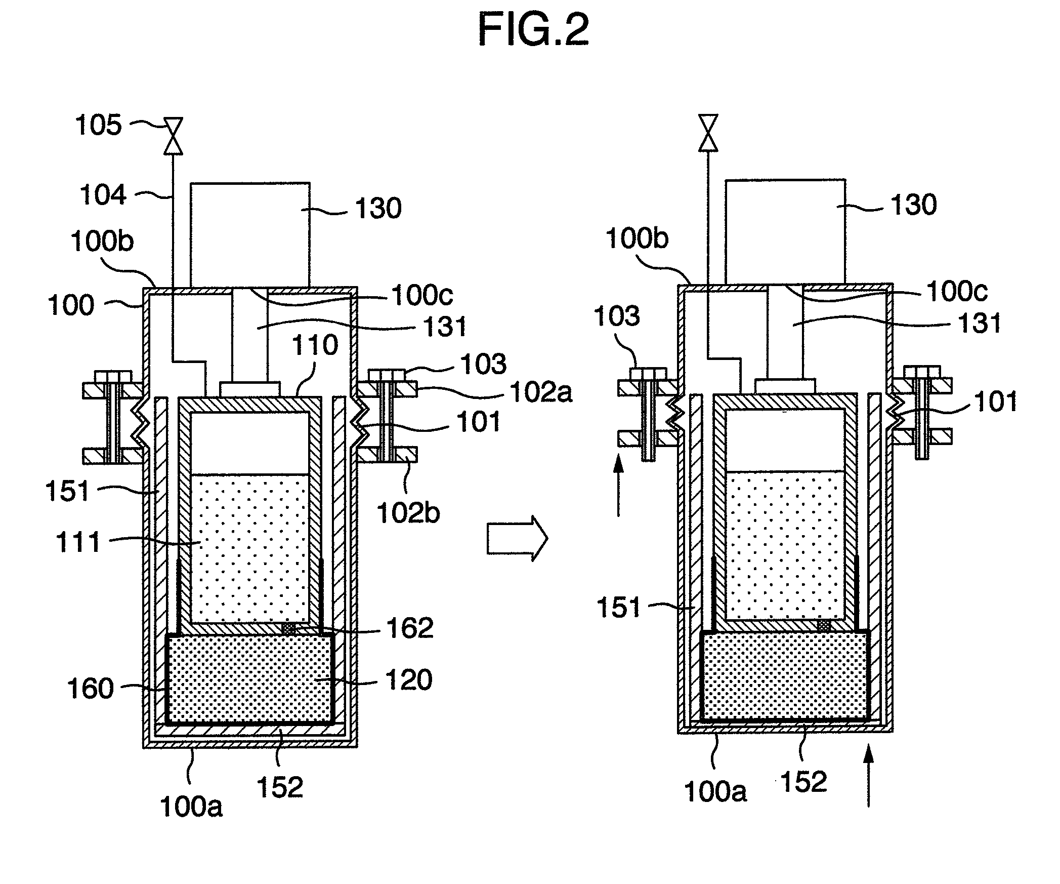
[0064]With the magnetic field generator the cooling member 132 at the lower end of the cooling head 131 and the hole 112 in the upper surface of the refrigerant vessel 110 are in thermal contact with each other. Contact surfaces of the both comprise a narrow ring-shaped tapered surfaces. An interior of the refrigerant vessel 110 is closed by the contact surfaces. When the cooling member 132 of the refrigerator 130 is cooled, nitrogen in the port 140 solidifies to intrude into a contact region between the cooling member 132 and the hole 112 of the refrigerant vessel 110. Thereby, thermal contact between the cooling member 132 at the lower end of the cooling head 131 and the hole 112 in the upper surface of the refrigerant vessel 110 becomes favorable and further the refrigerant vessel 110 is improved in quality of closeness. Thus, the refrigerant vessel 110 can be cooled by the refrigerator 130. At the same time, when an interior of the port 140 is cooled by the refrigerator 130 and...


PUM

PropertyMeasurementUnit
temperatureaaaaaaaaaa
critical temperatureaaaaaaaaaa

Abstract

A magnetic field generator comprises a superconducting bulk body, which generates a superconducting magnetic field, a refrigerant vessel for storing solid nitrogen, a vacuum container, which accommodates therein the superconducting bulk body and the refrigerant vessel, and a refrigerator having a cooling head for cooling the refrigerant vessel. The superconducting bulk body is arranged along a wall of the vacuum container. The cooling head of the refrigerator and the refrigerant vessel are in thermal contact with each other. The refrigerant vessel and the superconducting bulk body are in thermal contact with each other.

Description

BACKGROUND OF THE INVENTION[0001]The present invention relates to a magnetic field generator, which generates a magnetic field, and more particular, to a magnetic field generator, which uses a superconducting magnet.[0002]A superconducting magnet is used in MRI (Magnetic Resonance Imaging) apparatuses. The superconducting magnet is kept at extremely low temperature by liquid helium. The liquid helium is always cooled to temperatures equal to, or lower than its evaporating temperature.[0003]MRI apparatuses are constructed so as to normally function even when power goes down. Backup power supplies are provided in hospitals against power failure. Further, even when a refrigerator stops, the heat capacity of the liquid helium inhibits temperature rise of a superconducting magnet. Accordingly, even when a refrigerator stops due to power failure, it is possible to maintain the superconducting magnet in a superconductive state for about two or three days or more.[0004]JP-A-2005-116956 disc...

Claims


Application Information

Patent Timeline
Patent Type & Authority Patents(United States)
IPC IPC(8): H01F7/00H01F5/00H01F1/00H01F6/00H01F6/06
CPCH01F6/04Y10S505/892
Inventor ISOGAMI, HISASHISAHO, NORIHIDETANAKA, HIROYUKI
Owner HITACHI LTD
Why Eureka
Try Eureka