Undulator

a technology of undulator and magnet, which is applied in the field ofundulator, can solve the problems of demagnetization of permanent magnets and limit the characteristics of permanent magnets, and achieve the effect of improving radiation-proof characteristics and intensifying the magnetic field in spa

Active Publication Date: 2011-01-18
RIKEN +1
View PDF14 Cites 8 Cited by
  • Summary
  • Abstract
  • Description
  • Claims
  • Application Information

AI Technical Summary

Benefits of technology

[0015]Hereinafter, a description will be made of a function and an effect of the undulator having the above construction. In order to form a periodic magnetic field, the first magnetic circuit and the second magnetic circuit are arranged oppositely with the space therebetween. The first magnetic circuit is supported by the first support body and the second magnetic circuit is supported by the second support body. The first and second magnetic circuits are in-vacuumed in the vacuum chamber. When an electron beam is passed through the space in which the periodic magnetic field is generated, the synchrotron radiation can be generated. Each of the first and second magnetic circuits includes permanent magnets and the cooling mechanism for cooling the permanent magnet below the room temperature. When the permanent magnet is cooled, there appear characteristics in which a remanent flux density (Br) and magnetic coercive force (designated by iHc which is a value of H when an I-H curve (demagnetization curve) crosses an H axis and called intrinsic magnetic coercive force) are increased. When the remanent flux density is increased, magnetic characteristics are improved, so that an intense magnetic field can be formed in the space. In addition, when the magnetic coercive force is increased, it is known that radiation-proof characteristics are improved. As a result, when the first magnetic circuit and the second magnetic circuit are formed oppositely with the space therebetween, there can be provided an undulator in which the magnetic field formed in the space can be intensified and the radiation-proof characteristics can be improved.
[0041]When the permanent magnet is cooled, there is a permanent magnet which shows characteristics in which the remanent flux density is increased as the temperature is lowered, but when the temperature is lowered to a certain temperature or less, the remanent flux density is reduced. Therefore, when the magnetic circuit includes the permanent magnet, it is necessary to control the cooling temperature. Thus, since the heater for heating the magnetic circuit, the temperature sensor for detecting the temperature of the magnetic circuit, and the temperature control unit for controlling the heater are provided, the cooling temperature can be appropriately controlled.

Problems solved by technology

However, even when the gap is narrowed as described above, there is a limit in characteristics of the permanent magnet.
In addition, when the gap is narrowed too much, there arises a new problem such that the permanent magnet is demagnetized due to radiation generated when the electron beam impinges on the permanent magnet.

Method used


Image

  • Undulator
  • Undulator
  • Undulator

Examples


first embodiment

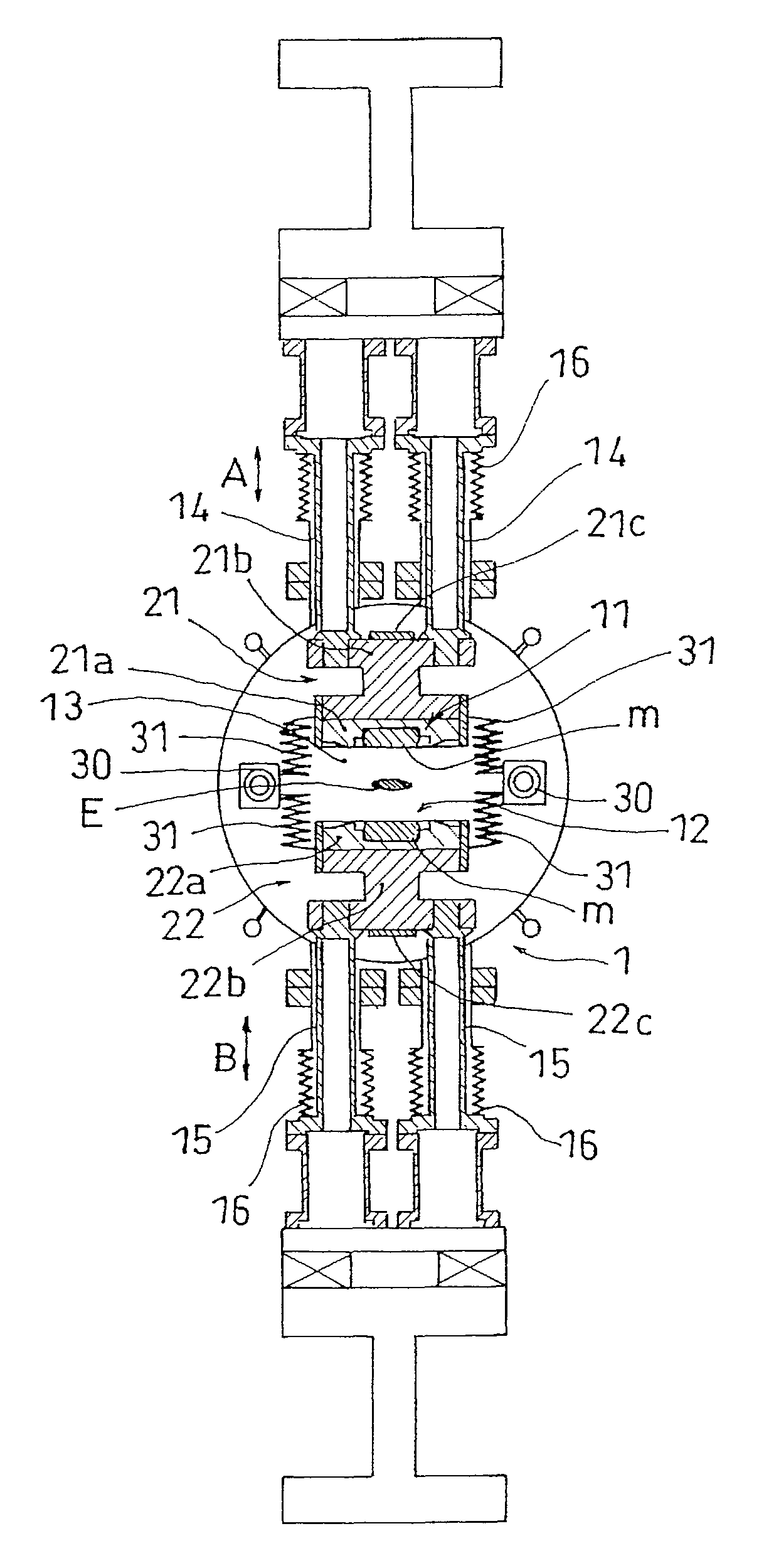
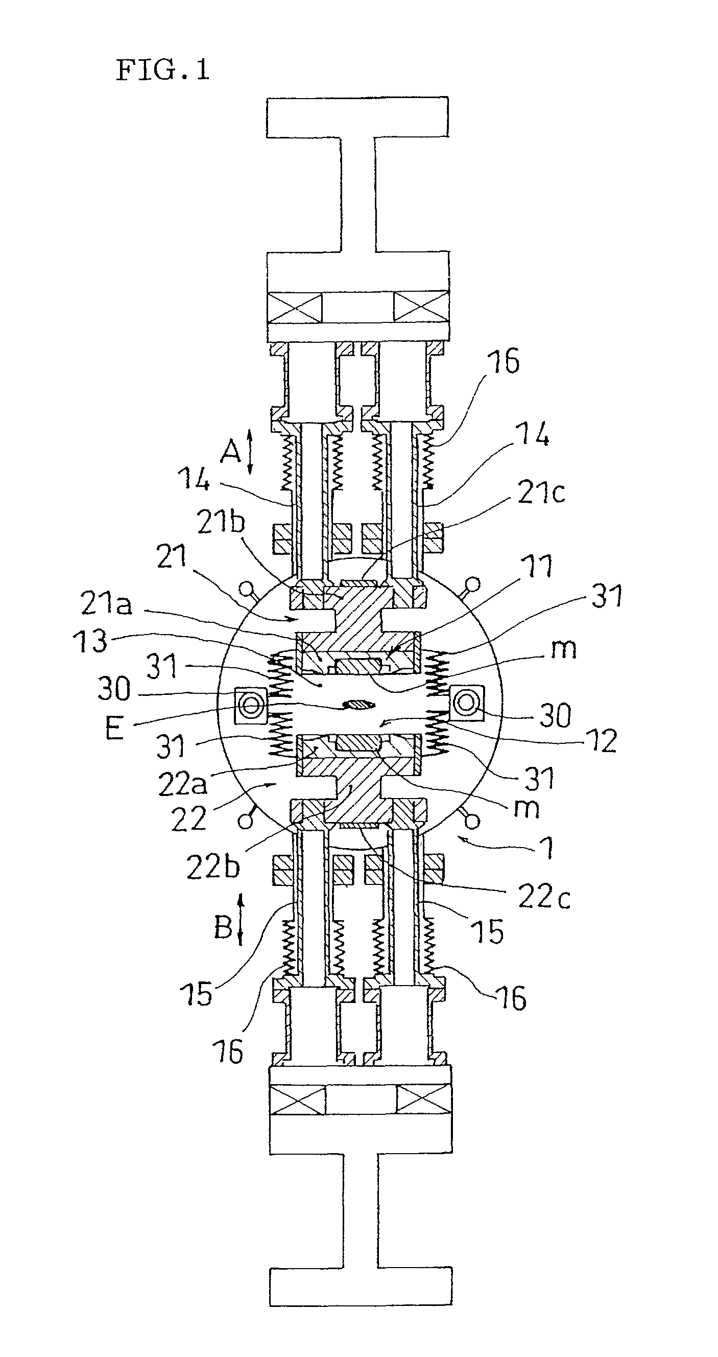
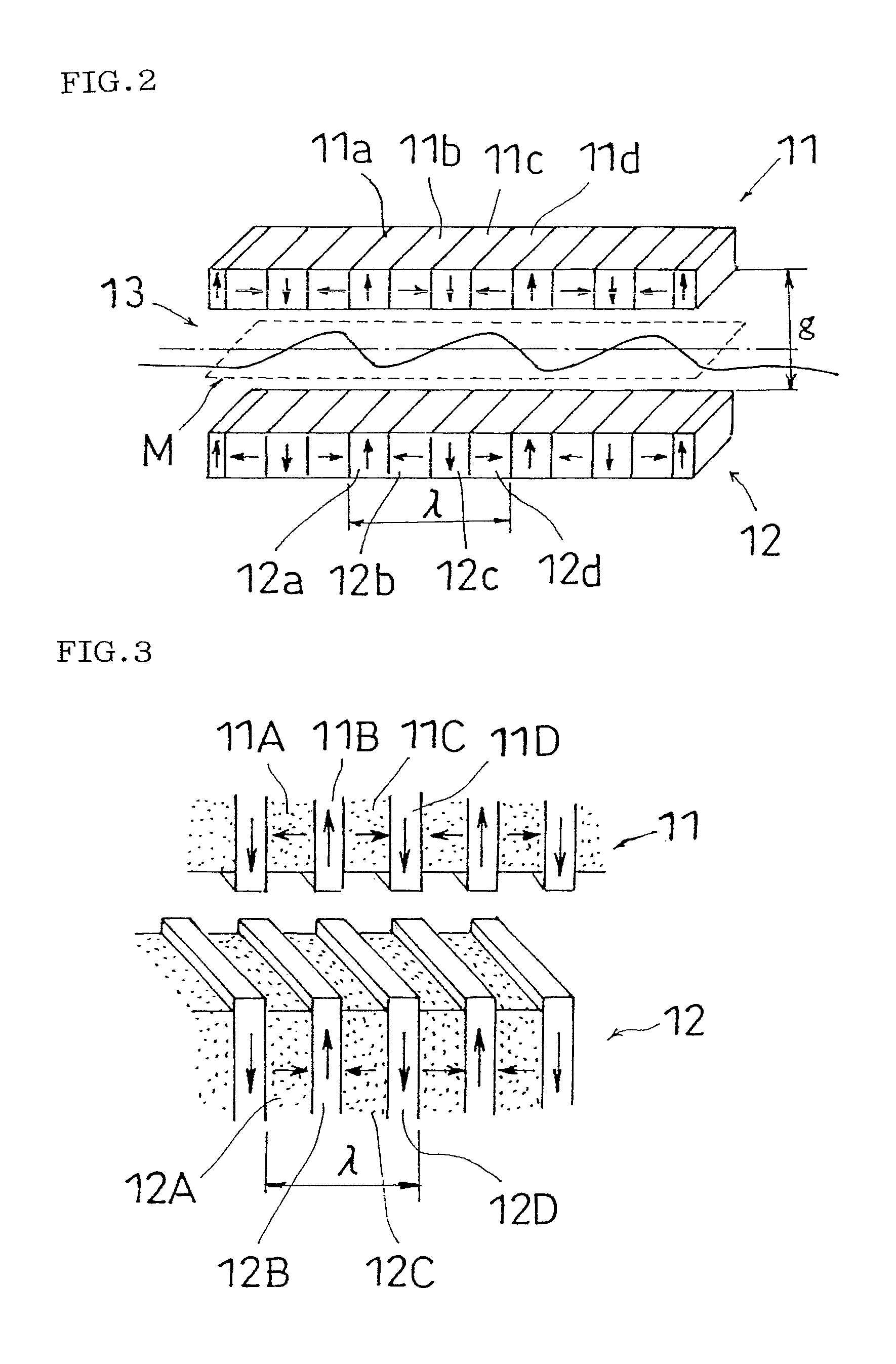
[0063]Next, a description will be made of a construction of the undulator according to a first embodiment. FIG. 1 is the transverse sectional view showing the undulator cut along a surface perpendicular to the traveling direction of the electron beam. The first magnetic circuit 11 and the second magnetic circuit 12 are oppositely arranged with the space 13 therebetween. As described above with reference to FIG. 2, according to the first magnetic circuit 11, many permanent magnets “m” are arranged along the traveling direction of the electron beam (direction perpendicular to a sheet surface of FIG. 1). Similarly, many permanent magnets “m” are arranged in the second magnetic circuit 12. A concrete example of a preferred permanent magnet “m” will be described below.

[0064]A first support body 21 is provided to mount and support the first magnetic circuit 11. The first support body 21 includes a first magnet holder 21a (corresponding to a holder) and a first magnet mounting beam 21b (co...

second embodiment

[0079]Hereinafter, a description will be made of an undulator according to a second embodiment with reference to FIG. 6. The same reference numbers are allotted to the components having the same functions as those in the first embodiment and their descriptions will not be repeated.

[0080]According to the second embodiment, a pair of first refrigerant passing tubes 30A and a pair of second refrigerant passing tubes 30B are provided and each first refrigerant passing tube 30A is connected to a first support body 21 through a connecting component 31A. Similarly, each second refrigerant passing tube 30B is connected to a second support body 22 through a connecting component 31B. Each of the connecting components 31A and 31B has flexibility. Thus, although each of the refrigerant passing tubes 30A and 30B is fixed to a vacuum chamber 1, even when the first and second support bodies 21 and 22 are vertically moved, connecting states between the support bodies 21 and 22 and the refrigerant p...

third embodiment

[0081]Hereinafter, a description will be made of an undulator according to a third embodiment with reference to FIG. 7. This embodiment is different from the second embodiment in that first and second refrigerant passing tubes 30A and 30B are fixed to first and second support bodies 21 and 22 through fixing units 32A and 32B. The fixing units 32A and 32B are formed of metal plate (such as a copper plate (beryllium copper and equivalent), a stainless plate or an aluminum plate). When the first support body 21 and the second support body 22 are vertically moved, the first refrigerant passing tube 30A and the second refrigerant passing tube 30B are also vertically moved, respectively. Therefore, a connecting component having flexibility is not used. In addition, when it is necessary for the fixing units 32A and 32B to have thermal resistance, it is preferable that those are formed of the stainless plate.


PUM

PropertyMeasurementUnit
temperatureaaaaaaaaaa
magnetic fieldaaaaaaaaaa
temperatureaaaaaaaaaa

Abstract

An undulator comprises a first magnetic circuit (11) for forming a periodic magnetic field, a first support body (21) for supporting the first magnetic circuit (11), a second magnetic circuit (12) arranged opposite to the first magnetic circuit (11), for forming a periodic magnetic field, a second support body (22) for supporting the second magnetic circuit (12), a space (13) formed between the oppositely arranged first magnetic circuit (11) and the second magnetic circuit (12), for passing an electron beam, a vacuum chamber (1) for vacuum-sealing the first magnetic circuit (11) and the second magnetic circuit (12), and a refrigerant passing tube (30) for cooling a permanent magnet (m) constituting the first magnetic circuit (11) and the second magnetic circuit (12) below the room temperature.

Description

[0001]This application is the U.S. National Phase under 35 U.S.C. §371 of International Application PCT / JP2005 / 000525, filed Jan. 18, 2005, which claims priority to Japanese Patent Application No. 2004-015878, filed Jan. 23, 2004. The International Application was not published under PCT Article 21(2) in English.TECHNICAL FIELD[0002]The present invention relates to an undulator comprising a first magnetic circuit for forming a periodic magnetic field, a first support body for supporting the first magnetic circuit, a second magnetic circuit arranged opposite to the first magnetic circuit, for forming a periodic magnetic field, a second support body for supporting the second magnetic circuit, a space formed between the oppositely arranged first and second magnetic circuits, for passing an electron beam, and a vacuum chamber for in-vacuuming the first magnetic circuit and the second magnetic circuit.BACKGROUND ART[0003]When an electron beam accelerated to about the speed of light in va...

Claims


Application Information

Patent Timeline
Patent Type & Authority Patents(United States)
IPC IPC(8): H01F7/02G21K1/00G21K1/093H05G2/00H05H13/04
CPCH05G2/00H05H7/04
Inventor KITAMURA, HIDEOHARA, TORUTANAKA, TAKASHIKOHDA, TSUTOMUMATSUURA, YUTAKA
Owner RIKEN
Why Eureka
Try Eureka