Activation apparatus

Inactive Publication Date: 2005-11-24
ITABASHI KAZUKO
View PDF3 Cites 0 Cited by
  • Summary
  • Abstract
  • Description
  • Claims
  • Application Information

AI Technical Summary

Benefits of technology

[0006] An object of the present invention is to solve the above-described problem, and to efficiently activate an object by a simple device which does not require any new energy source and which is easily attached without inhibiting operation of each system. For example, fuel consumption is improved in fuel, absorption in a human body is facilitated without polluting any city water pipe in water, oxidation is prevented in oil, viscosity is lowered to thereby improve circulation in blood, and minus ionization or the like is achieved in air.
[0007] According to the present invention, there is provided an activation apparatus wherein two or more types of metals or materials mainly containing metals, having different standard electrode potentials, are stacked upon one another to generate electric charges, and accordingly electromagnetic waves are generated by a potential difference between the stacked metals or materials. Consequently, even with a lightweight and simple constitution, taken energy is large, large potential difference and intense magnetic field are caused, and ions are generated, so that the object can be efficiently activated. Here, in the present invention, it is assumed that the material mainly containing the metal include an organic or inorganic metal compound and a mixture mainly of the metal.
[0009] Moreover, at least one of minerals, ceramics, sludge of them, and metal sludge is held between two or more types of metals. Then, an activation apparatus is obtained in which the metals are electrically separated or interposed from one another, the generated magnetic field is adjusted, and a far infrared effect is strengthened. Efficiency of a magnetic force line effect by the magnetic field can be expected, and further activation of an object by the far infrared effect can also be expected.
[0010] Furthermore, when the above-described laminate is formed into a plate, band, or sheet shape, an energy take-in area can be broadened, and a function area can be broadened. Additionally, when the laminate is arched, the magnetic force line effect and far infrared effect can be concentrated on a portion surrounded with the laminate. When the laminate is formed into a tubular shape, further the effect can be concentrated on a central portion, and the activation apparatus can be compact and easily attached to the curved face of a tubular member. It is to be noted that examples of the tubular member include small-diameter pipes and beads. These members can be easily connected to one another via threads or the like, and easily attached to a target. Furthermore, when the apparatus is formed into a round shape in the connected state, the effects can be concentrated on a middle portion. Additionally, a reflective member which reflects an electromagnetic wave is disposed on one surface of the laminate, the generated electromagnetic wave is concentrated on one direction or point, and accordingly fluid can be activated more efficiently.

Problems solved by technology

However, since a flow rate of a fuel flowing through an oil supply tube is remarkably slow, energy is remarkably small, and intensity of the magnetic field by the magnetic member is also small.
Therefore, a constitution is complicated, size or weight is excessively large, the constitution is not easily attached to the existing system, or a necessity for stopping the operation for the attaching occurs.
The techniques have had low practicability, and have not easily spread.
However, since one unit of the magnetic member or the magnetic material is small, and surface area of a portion for taking the energy from the outside is small, generated magnetic field or minus ion amount is small, and it has been difficult to sufficiently reform blood.

Method used


Image

  • Activation apparatus
  • Activation apparatus
  • Activation apparatus

Examples


Embodiment Construction

[0014] A best mode for carrying out the present invention will be described hereinafter in detail with reference to the drawings. It is to be noted that even in different embodiments, the same constituting elements are denoted with the same reference numerals, and described.

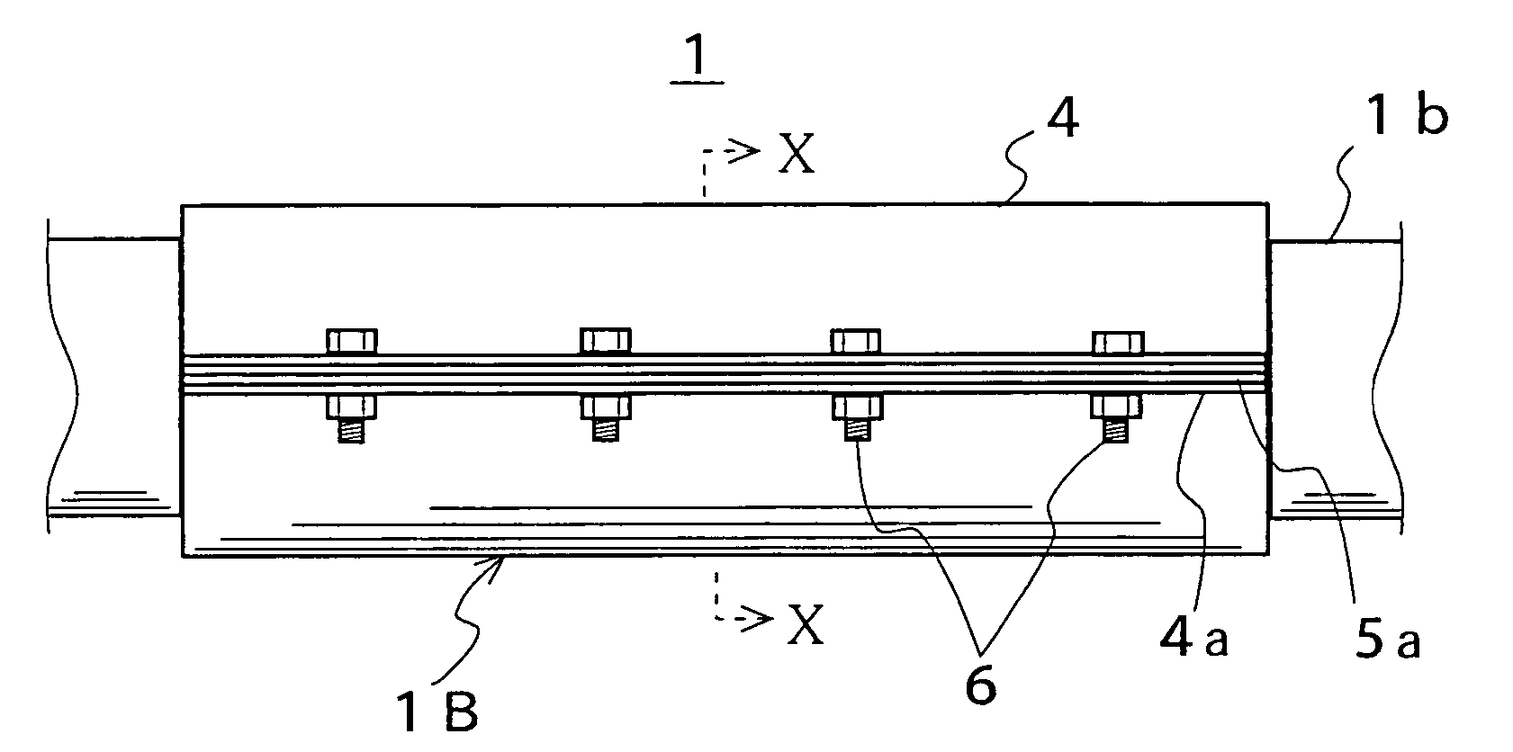
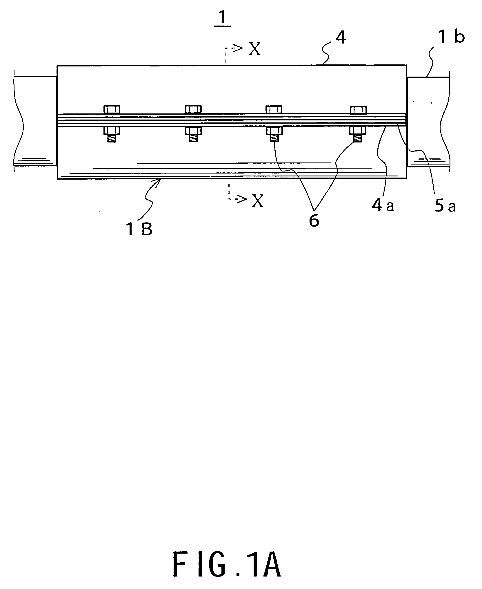
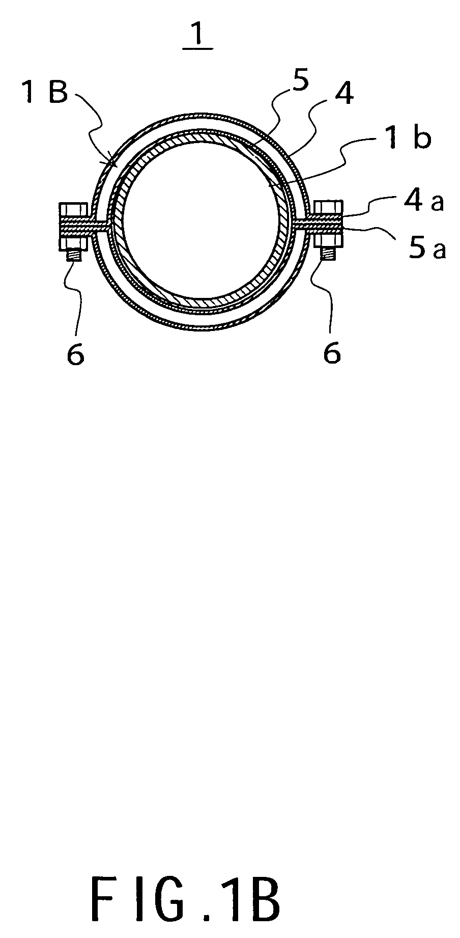
[0015]FIG. 1 shows a best mode for carrying out the present invention. The drawing shows an activation apparatus 1, and one example of a fuel activation apparatus attached around a fuel transport pipe 1b connecting a fuel tank to a motor. FIG. 1A is a front view, and B is an X-X line sectional view. The activation apparatus 1 is constituted by forming a layered body 1B into a tubular form, in which two types of metal plates having different potentials are formed into a two-layer structure. For example, an outer-layer metal plate 4 is formed of titanium having a high minus potential, and an inner-layer metal plate 5 is formed of copper having a low minus potential to thereby dispose a potential difference. Each o...


PUM


Abstract

An activation apparatus (1) is characterized in that two or more of metals or materials mainly containing metals which have different standard electrode potentials are stacked to thereby generate electric charges, and electromagnetic waves are generated by a potential difference between the stacked metals or materials. For example, a layered body (1B) of a two-layer structure having an outer layer metal plate (4) of titanium and an inner layer metal plate (5) of copper is formed into a tubular shape. The layered body is so fixed around a fuel transport pipe (1b) via a plurality of bolts nuts (6) that the outer layer metal plate (4) and the inner layer metal plate (5) divided into two rainwater gutter-like shapes and comprising flanges (4a), (5a) of a joint portion form a two-layer structure having a predetermined space therebetween. The apparatus does not need a new energy source, and is an easily attachable, simple apparatus. The apparatus efficiently activates a fuel to thereby improve fuel consumption.

Description

TECHNICAL FIELD [0001] The present invention relates to an activation apparatus which enhances functions of objects including liquids such as water, oil (including volatile oils such as gasoline), gases such as air, gas, solids such as foods, and mixtures such as human bodies by activation of the objects. BACKGROUND ART [0002] A technique has heretofore been put into practical use in which a magnetic field or an electric charge is applied to fluids such as water and fuel, a cluster of these molecules is decomposed and formed into a fine-grained structure to enhance reactivity, or fluid molecules are ionized to thereby reform them. For example, in a technique described in Japanese Patent Application Laid-Open No. 7-258657, a plurality of magnetic members having predetermined thicknesses are continuously arranged in a direction in which magnetisms repulse each other to thereby generate a predetermined magnetic field, and disposed in a fuel tank. Accordingly, carbon hydride molecules o...

Claims


Application Information

Patent Timeline
IPC IPC(8): B01J19/12C02F1/00C02F1/48F02M27/04
CPCB01J19/12B01J2219/0809B01J2219/083B01J2219/0835F02M27/04B01J2219/0843B01J2219/0877C02F1/005C02F1/48B01J2219/0841
Inventor ITABASHI, KAZUKO
Owner ITABASHI KAZUKO
Why Eureka
Try Eureka