Coil capable of generating a magnetic field and method of manufacturing said coil

a technology of magnetic field and coil, which is applied in the direction of magnets, inductances, magnetic bodies, etc., can solve the problems of non-homogeneity of magnetic field, lack of machine reliability, and deformation of coil turns, and achieve the effect of simple design

Inactive Publication Date: 2012-11-13
CENT NAT DE LA RECHERCHE SCI
View PDF7 Cites 4 Cited by
  • Summary
  • Abstract
  • Description
  • Claims
  • Application Information

AI Technical Summary

Benefits of technology

[0014]One of the aims of the invention is therefore to rectify all these disadvantages by proposing a coil or a set of coils capable of generating a magnetic field and particularly capable of generating an intense magnetic field, and a method for manufacturing such coil of simple design, which is straightforward and absorbs stresses caused by electromagnetic forces on the turns of the coils.
[0022]In addition, the successive bosses on a given turn can be advantageously spaced angularly to optimise absorbing electromagnetic stresses and prevent excessive deformations of turns.
[0029]Advantageously, the successive bosses on a turn are angularly offset to optimise absorbing electromagnetic stresses and prevent excessive deformations of turns.

Problems solved by technology

Gradient coils of magnetic fields or those generating an intense magnetic field are subjected to intense electromagnetic forces which cause mechanical stresses leading to deformation of the turns of the coil.
Deformation of the turns can cause a lack of reliability of the machine and / or non-homogeneity of the magnetic field detrimental to high-quality imaging production.

Method used


Image

  • Coil capable of generating a magnetic field and method of manufacturing said coil
  • Coil capable of generating a magnetic field and method of manufacturing said coil
  • Coil capable of generating a magnetic field and method of manufacturing said coil

Examples


Embodiment Construction

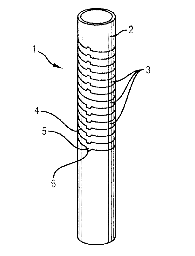
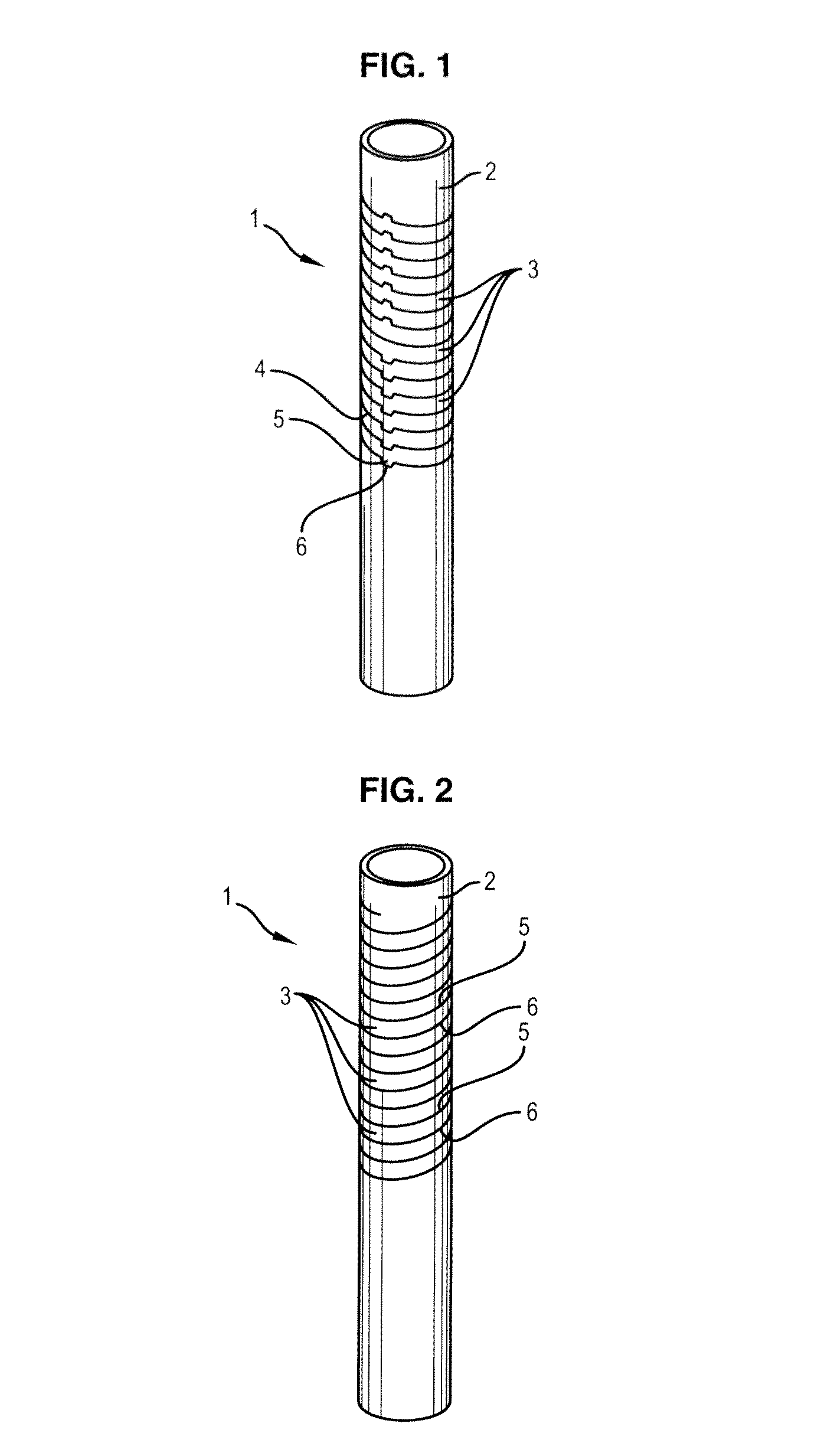
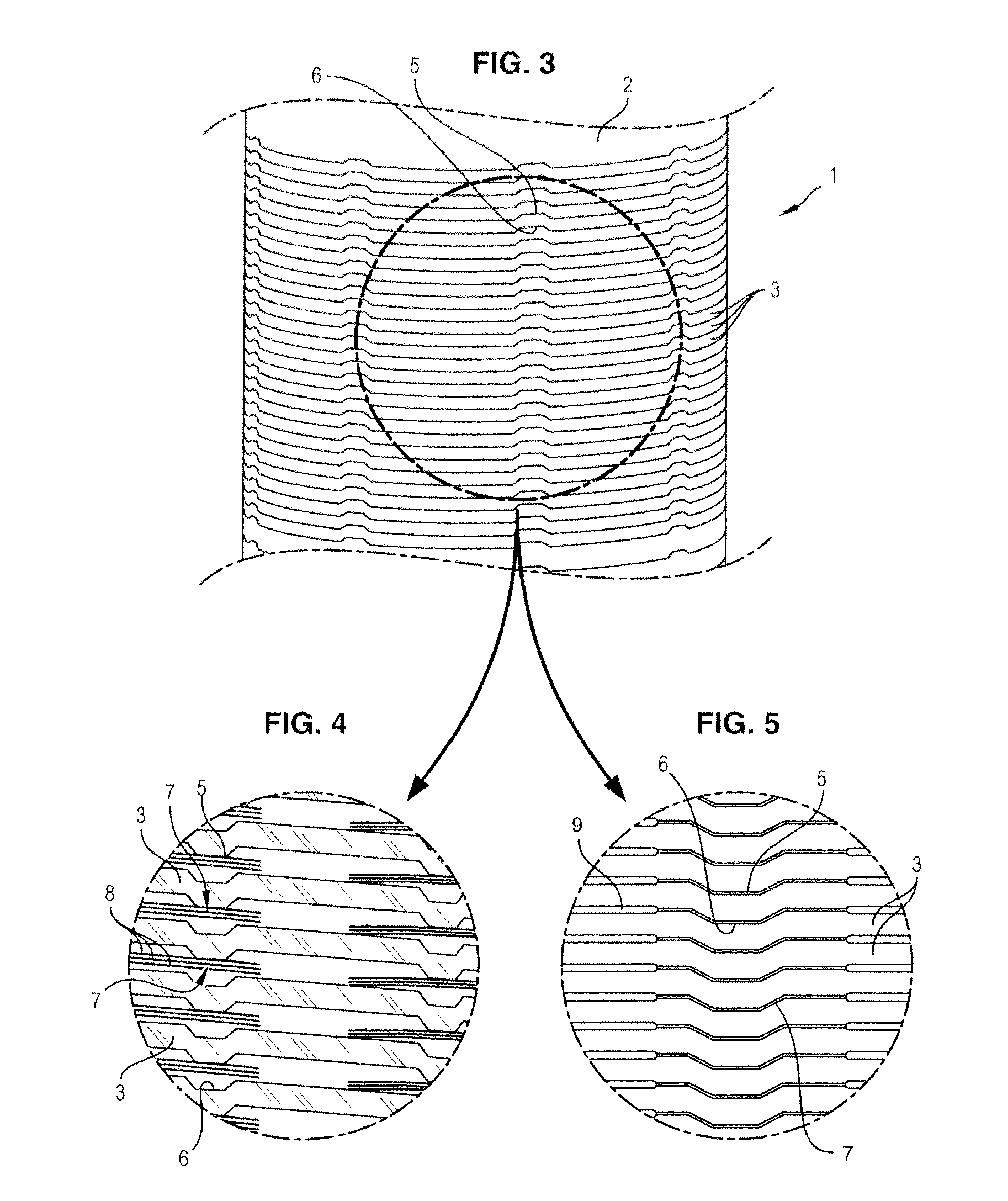
[0048]In reference to FIG. 1, the coil 1 comprises an overall cylindrical tube 2 in which turns 3 have been formed using any appropriate cutting means along a helicoidal cut-out line 4, said tube 2 being made of electrically conductive material such as copper or a bulk superconducting for example, and said coil optionally comprising insulating material covering the cut-out line 4 in a way known to the person skilled in the art.

[0049]The tube 2 provided with turns 3 can constitute the coil 1 as such. However, according to another embodiment, the tube with the turns constitutes a support for a winding, this “support+winding” assembly forming said coil. In the case of a superconducting magnet, the winding can for example be formed by a superconducting band or wire (for example comprising an alloy of type NbTi, Nb3Sn, Nb3Al, or YBaCuO) surrounding the tube cut out in a spiral. Therefore the tube serves as mechanical support for the band or wire and is also used in thermal regulation of ...


PUM

PropertyMeasurementUnit
magnetic fieldaaaaaaaaaa
mechanical stressesaaaaaaaaaa
temperatureaaaaaaaaaa

Abstract

A method for manufacturing a coil capable of generating a magnetic field known as an intense field when an electric current passes through it. There is formed at least one boss on at least one turn of the coil and at least one recess of a corresponding form in an adjacent turn, such that the boss extends perpendicularly to the recess for absorbing the mechanical stresses caused by the electromagnetic forces and mechanical forces of thermal origin. The coil is capable of generating a magnetic field known as an intense field when an electric current passes through it. The coil includes a tube made of a conductive material and cut out along an overall helicoidal cut-out line. At least one turn of the coil includes at least one boss extending perpendicularly to a recess of a corresponding form in an adjacent turn.

Description

[0001]This is a Continuation-in-Part application of International Application Number PCT / EP2008 / 064338, filed Oct. 23, 2008.FIELD OF THE INVENTION[0002]The present invention relates to a coil capable of generating a magnetic field adapted in particular for generating intense magnetic fields and / or for performance under large mechanical stresses, and a method for manufacturing said coil.BACKGROUND OF THE INVENTION[0003]In the field of magnetic field production, it is well known to generate an intense magnetic field by “magnets” constituted by one or more coils through which an intense electric current passes, said coils being cooled.[0004]Said coils are generally constituted by cylindrical tubes made of conductive or superconducting material and cut out along an overall helicoidal cut-out line, at constant pitch or not, to form turns.[0005]These coils for intense fields are currently almost exclusively used in intense magnetic field laboratories and could be of use for example in NMR...

Claims


Application Information

Patent Timeline
Patent Type & Authority Patents(United States)
IPC IPC(8): H01F7/06H01F27/28
CPCH01F7/202H01F41/04H01F27/34Y10T29/4902H01F41/122
Inventor DEBRAY, FRANCOISPFISTER, ROLFDUMAS, JEANTROPHIME, CHRISTOPHEVIDAL, NADINETUDELA, JEAN-MARC
Owner CENT NAT DE LA RECHERCHE SCI
Why Eureka
Try Eureka