Display device, method of manufacturing display device and electronic apparatus

a display device and electronic equipment technology, applied in the direction of static indicating devices, instruments, optics, etc., can solve the problems of inferior reproducibility, difficult to obtain a specific intermediate tone of gray color or other colors of specified gradation, and difficult to obtain gray color of specified gradation. , to achieve the effect of excellent display performan

Inactive Publication Date: 2010-07-27
SEIKO EPSON CORP
View PDF7 Cites 8 Cited by
  • Summary
  • Abstract
  • Description
  • Claims
  • Application Information

AI Technical Summary

Benefits of technology

[0021]It is an object of the present invention to provide a display device capable of easily and reliably obtaining an intermediate tone and reliably maintaining individual colors including the intermediate tone even at stoppage of application of an electrical voltage, a manufacturing method of a display device capable of easily and reliably manufacturing the display device, and an electronic apparatus provided with the display device.

Problems solved by technology

In the conventional electrophoretic display devices, however, it is difficult to obtain a specific intermediate tone of a gray color or other colors of specified gradation.
This leads to inferior reproducibility and makes it very difficult to obtain a gray color of specified gradation.
Even if the gray color is obtained by stoppage of the application of the electrical voltage to the pair of electrodes, such a state is unstable and is changed over time.
For these reasons, even if the gray color of the specified gradation is obtained, the gray color cannot be maintained as it is and thus a displayed image becomes highly unstable.
This makes a control operation and a structure of the conventional electrophoretic display device complicated, and leads to increased power consumption thereof.
Further, the adsorption particles are adsorbed to the inner surface of the wall portion so that they are hard to adhere to each other.

Method used


Image

  • Display device, method of manufacturing display device and electronic apparatus
  • Display device, method of manufacturing display device and electronic apparatus
  • Display device, method of manufacturing display device and electronic apparatus

Examples


first embodiment

1. Display Device

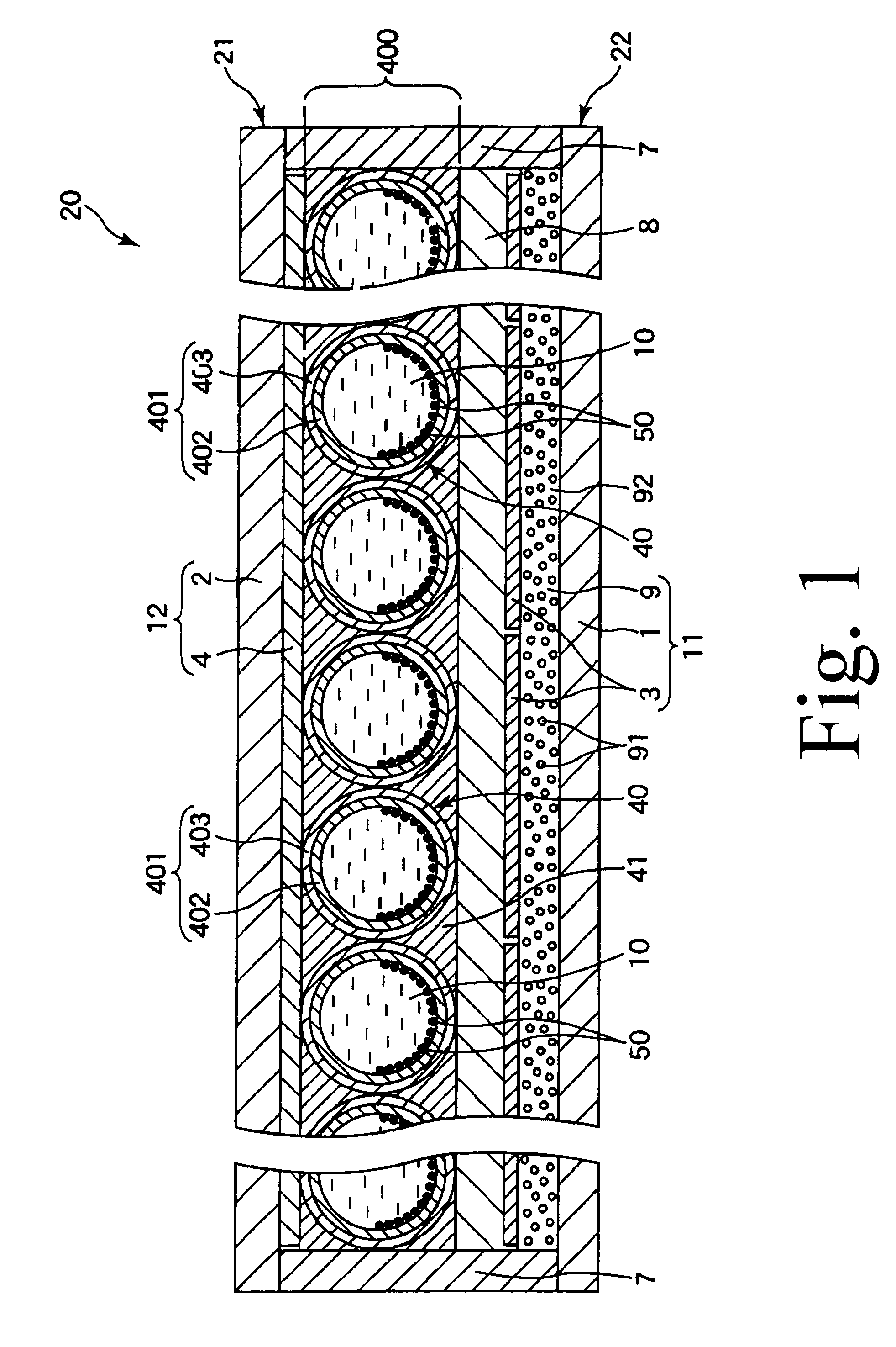
[0073]First, description will be made on the display device according to the present invention.

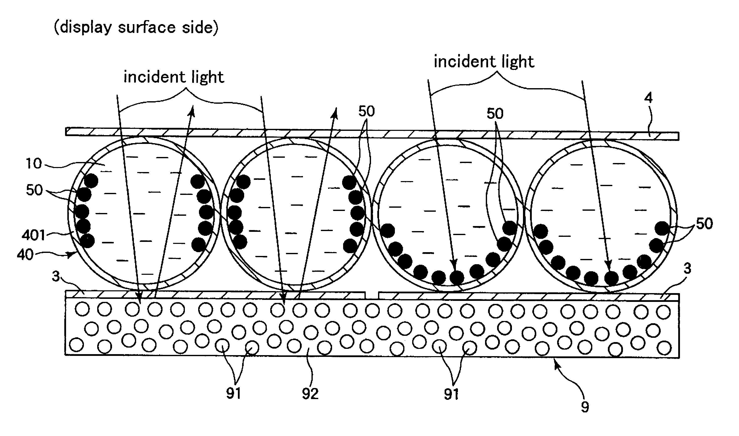
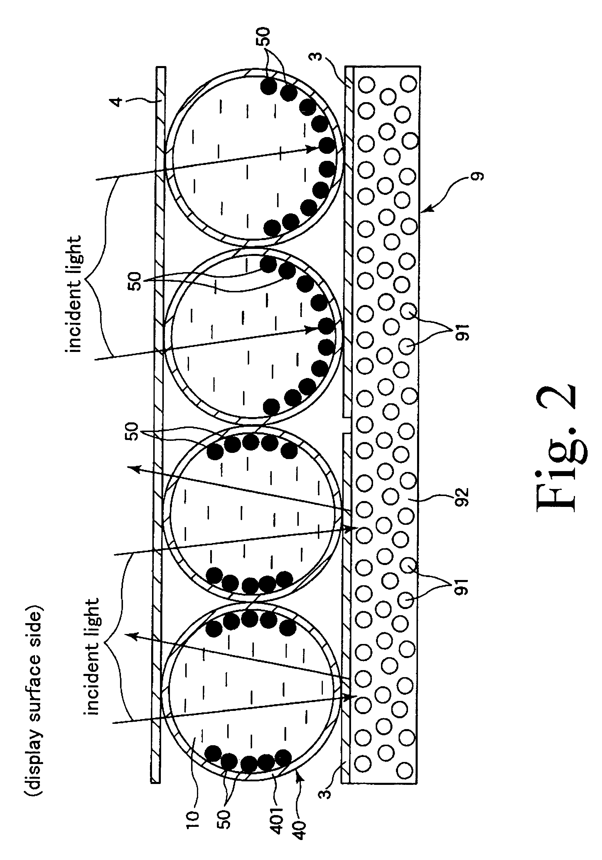
[0074]FIG. 1 is a vertical section view schematically showing a first embodiment of the display device according to the present invention. FIGS. 2, 3A to 3C and 4 are pattern diagrams for explaining behavior of the display device shown in FIG. 1.

[0075]FIG. 5 is a graph (a potential curve) showing a relationship of a distance between a surface of each of adsorption particles and an inner surface of a capsule body to potential of the adsorption particle in the display device shown in FIG. 1.

[0076]FIG. 6 is a pattern diagram for explaining behavior of the display device shown in FIG. 1. FIGS. 7A to 7D and 8E to 8G are pattern diagrams for explaining a method of manufacturing the display device shown in FIG. 1.

[0077]Hereinafter, the upper side in each of FIGS. 1, 2, 3A to 3C, 4, 6, 7A to 7D and 8E to 8G will be referred to as “upper” and the lower side will be referred to as “...

second embodiment

[0281]Hereinafter, a second embodiment will be described, with emphasis placed on the differing points from the first embodiment but with no description made on the same matters.

[0282]In a method of manufacturing a display device 20 of the second embodiment, the capsule body 401 is not electrically charged when forming the same. After the capsule body 401 has been formed in its entirety, namely after the microcapsule production step [A1] has been completed, a charging step for electrically charging the capsule body 401 with the opposite polarity to the adsorption particles 50 through the binder 41 is performed in the microcapsule-containing dispersion liquid preparation step [A2] (that is, when preparing the microcapsule dispersion liquid).

[0283]In this case, a specified amount of positive or negative charging agent may be added to the binder 41 depending on the polarity of the adsorption particles 50. This makes it possible to adjust the charge amount and the charge density of the ...

third embodiment

[0285]FIG. 9 is a vertical section view schematically showing a third embodiment of a display device according to the present invention. In the following description, the upper side in FIG. 9 will be referred to as “upper” with the lower side as “lower”, for the purpose of convenience in description.

[0286]Hereinafter, the third embodiment will be described, with emphasis placed on the differing points from the first embodiment but with no description made on the same matters.

[0287]As shown in FIG. 9, a display device 20 of the third embodiment includes a color filter 13 provided between the first electrodes 3 (the microcapsule-containing layer 400) and the reflector 9, which makes it possible to provide color display. Particularly, different kinds of the color display can be provided by arbitrarily setting construction (e.g., kinds of colors and the number of colors) of the color filter 13.

[0288]The color filter 13 is not particularly limited to a specific type, but may be, e.g., of...


PUM

PropertyMeasurementUnit
thicknessaaaaaaaaaa
thicknessaaaaaaaaaa
thicknessaaaaaaaaaa

Abstract

A display device capable of easily and reliably obtaining an intermediate tone and reliably maintaining individual colors including the intermediate tone even at stoppage of application of an electrical voltage, a manufacturing method of a display device capable of easily and reliably manufacturing the display device, and an electronic apparatus provided with the display device are provided. The display device has a display surface. The display device includes an adsorption particle-containing layer including a wall portion with an inner surface for defining a space, a plurality of electrically charged adsorption particles provided within the space in an adsorbed state that they are adsorbed to the inner surface of the wall portion, and a substantially transparent medium provided within the space, and a pair of electrodes that, when applied with an electrical voltage, generate electrical fields to act on the adsorption particles, wherein in the case where the electrical voltage is applied to between the electrodes, the adsorption particles are moved along the inner surface of the wall portion while maintaining the adsorbed state.

Description

CROSS-REFERENCE TO RELATED APPLICATION[0001]This application claims a priority to Japanese Patent Application No. 2007-299709 filed on Nov. 19, 2007 which is hereby expressly incorporated by reference herein in its entirety.BACKGROUND[0002]1. Technical Field[0003]The present invention relates to a display device, a method of manufacturing a display device and an electronic apparatus, and more specifically relates to a display device, a method of manufacturing the display device and an electronic apparatus provided with the display device.[0004]2. Related Art[0005]It is generally known that, if electrical fields are allowed to act on a dispersion system in which fine particles are dispersed in a liquid, the fine particles move (or migrate) in the liquid by a Coulomb force (an electrostatic force). This phenomenon is referred to as electrophoresis. In recent years, an electrophoretic display device that displays desired information (images) using the electrophoresis draws attention as...

Claims


Application Information

Patent Timeline
Patent Type & Authority Patents(United States)
IPC IPC(8): G02B26/00G02F1/167G02F1/16757G02F1/1677G02F1/1679
CPCG02F1/167G09G3/344G02F2001/1678G02F2201/34G02F2203/03G02F1/16757G02F1/1679G02F1/1677
Inventor KAWASE, TAKEOKOMATSU, HARUNOBUYAMAMOTO, HITOSHIMATSUMOTOKUSHINO, MITSUOKUWAMOTO, TOMOYUKIMATSUSHITA, TERUKI
Owner SEIKO EPSON CORP
Why Eureka
Try Eureka