
Electronic device display apparatus

a technology of electronic devices and display devices, applied in the direction of telephone set constructions, transmissions, substation equipment, etc., can solve the problems of unsuitably designed display pieces in and of themselves, and achieve the effect of reducing visual clutter, enhancing display properties of apparatus, and reducing the muffling of incoming and outgoing sound

Inactive Publication Date: 2010-08-03
GLOEDE PETER +1
View PDF21 Cites 5 Cited by
  • Summary
  • Abstract
  • Description
  • Claims
  • Application Information

AI Technical Summary

Benefits of technology

[0008]It is a further object of the present invention to provide an electronic device display apparatus that can take on the appearance of an unrelated object and accommodate a variety of cellular telephone or other electronic devices.
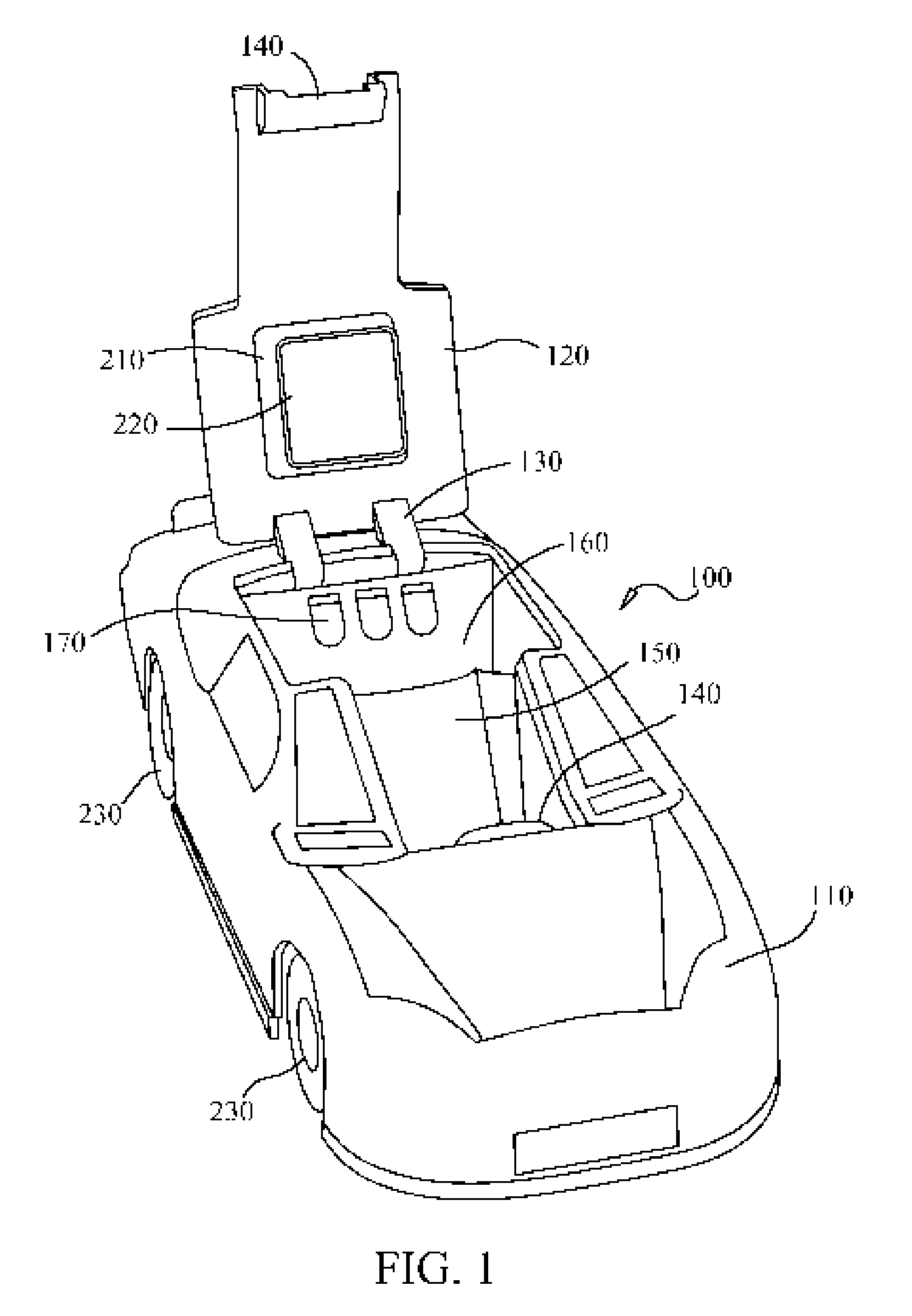
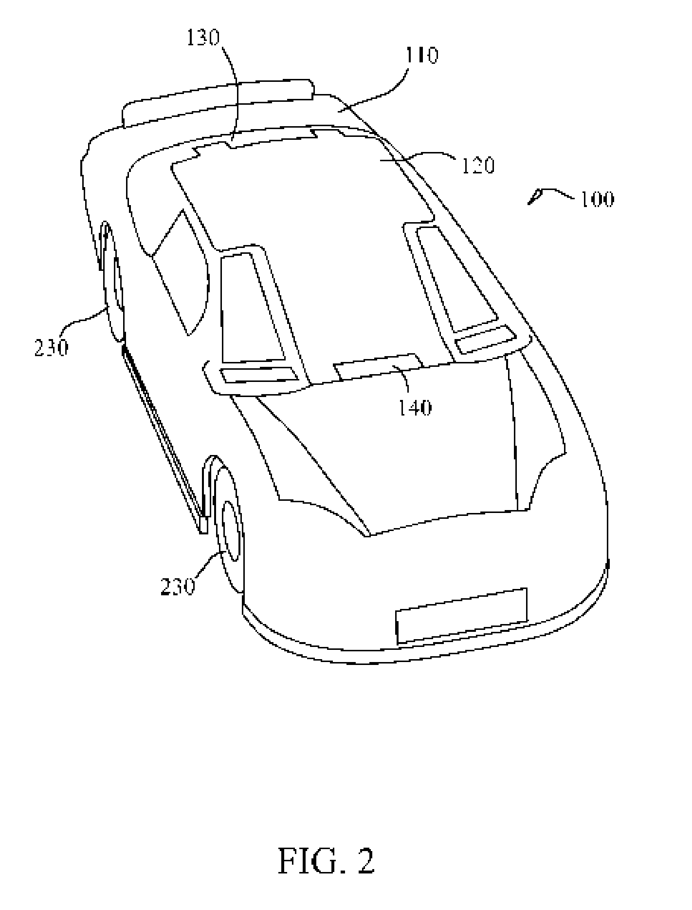
[0010]A portion of the upper surface is moveable. The movable surface can be connected to the apparatus by a hinge at one end of the movable surface. Another end of the movable surface can be releasably secured to the apparatus by a latch. When in a closed position, the movable surface completes the upper surface and further enhances the display properties of the apparatus. In various preferred embodiments a portion of the movable surface has an electronic device back support, which helps maintain the electronic device at a desired display position.
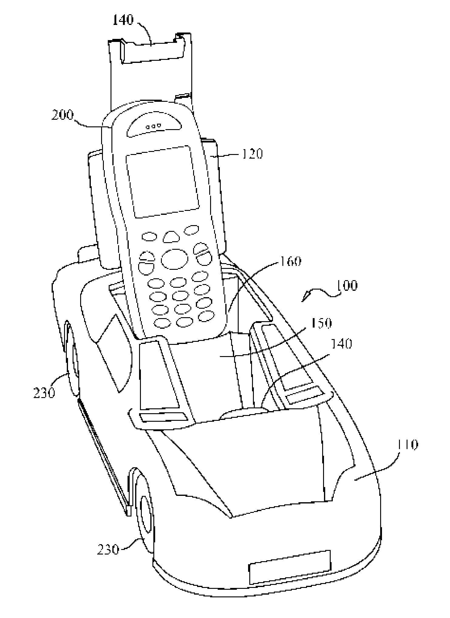
[0011]When in an open position, the apparatus is suitable for holding and displaying an electronic device, such as a cellular telephone, a personal digital assistant, or a portable digital music player. Interior to the apparatus are one or more electronic device supporting surfaces. The electronic device supporting surfaces are concealed when the movable surface is in the closed position and accessible when the movable surface is in the open position. The electronic device supporting surfaces support the electronic device at the desired display position. In various preferred embodiments, there can be one or more speakerphone vents at desired locations. Speakerphone vents can reduce the muffling of incoming and outgoing sound when the electronic device is cellular telephone being used in a speakerphone mode. Thus, the electronic device as a cellular telephone can be used in speakerphone mode while being displayed in the apparatus.
[0012]Also interior to the apparatus is a passage which permits a user to thread or otherwise route a cord, such as a battery charging cord or a computer connecting cord, into the apparatus and thus allow the electronic device to be charged or otherwise connected while being displayed. The passage is concealed when the movable surface is in the closed position and accessible when the movable surface is in the open position. Having a passage for a cord allows the apparatus to be used with a variety of electronic devices without redesign and without reproduction of the various electrical connectors found in electronic device cradles and battery charging stands.
[0013]The theme of the apparatus taking on the appearance of an unrelated object can be continued onto the underside of the apparatus. The apparatus has a bottom surface which can resemble the underside of the unrelated object. In various preferred embodiments disposed, molded, or otherwise created within bottom surface is a cord recess for threading or otherwise routing and preferable removably securing the cord. Removably securing the cord in the cord recess can prevent the cord from unintentionally sliding or otherwise becoming dislodged from its desired location and can reduce the visual clutter often caused by the myriad of cords and cables often associated with electronic devices by concealing the a portion of the cord within the apparatus.

Problems solved by technology

While this cradle is suitable for its intended purpose, namely receiving and supporting a portable electronic device, the cradle is not suitably designed as a display piece in and of itself.

Method used


Image

  • Electronic device display apparatus
  • Electronic device display apparatus
  • Electronic device display apparatus

Examples


Embodiment Construction

[0019]While this invention is susceptible of embodiments in many different forms, there is shown in the drawings and will herein be described in detail preferred embodiments of the invention with the understanding that the present disclosure is to be considered as an exemplification of the principles of the invention and is not intended to limit the broad aspect of the invention to the embodiments illustrated.

[0020]The present invention is an electronic device display apparatus 100 which takes on the appearance of an unrelated object. FIG. 1 shows a front upper perspective view of an electronic device display apparatus according to the present invention having a movable surface in an open position. FIG. 2 shows a front upper perspective view of an electronic device display apparatus according to the present invention having the movable surface in a closed position. The electronic device display apparatus 100 has an upper surface 110, wherein the upper surface 100 is shaped to resemb...


PUM


Abstract

A display apparatus for an electronic device which takes on the appearance of an unrelated object is disclosed. The electronic device display apparatus has an upper surface, wherein the upper surface is shaped to resemble an unrelated object. A portion of the upper surface is moveable between an open position and a closed position. When closed, the movable surface completes the upper surface and further enhances the display properties of the device. When open, the device is suitable for holding and displaying an electronic device. Interior to the apparatus are one or more electronic device supporting surfaces to support the electronic device at the desired display position. Also interior to the apparatus is a passage which permits a user to thread or otherwise route a battery charging cord into the apparatus. The apparatus also has a bottom surface which can resemble the underside of the unrelated object.

Description

BACKGROUND[0001]The present invention relates to an electronic device display apparatus, and more specifically to an electronic device display apparatus, particularly a cellular telephone display apparatus, having a hinged top and taking on the appearance of an unrelated object.DESCRIPTION OF THE RELATED ART[0002]Cellular telephones and similar wireless or radio telephones are commonplace today. In many instances people have foregone the traditional hard wired telephone and rely solely on their wireless telephone. As technology has advanced, the size of these telephones has been reduced. When not being carried on the body of the user, these telephones are often left on a desk, a counter, on a vehicle dashboard or console, in a purse, in a backpack or some other place.[0003]Various holders for these types of telephones and other electronic devices, such as personal digital assistants and portable digital music players, have been developed. These holders allow the user to place the te...

Claims


Application Information

Patent Timeline
Patent Type & Authority Patents(United States)
IPC IPC(8): H04M1/00
CPCH04M1/04H02J7/0044
Inventor GLOEDE, PETERJOHNSON, ROBERT
Owner GLOEDE PETER
Learn More