Vehicle steering column structure
a technology of steering column and release mechanism, which is applied in the direction of steering column, steering parts, vehicle components, etc., can solve the problems of uneasy driving of the steering column structure, and achieve the effect of consistent biasing for
- Summary
- Abstract
- Description
- Claims
- Application Information
AI Technical Summary
Benefits of technology
Problems solved by technology
Method used
Image
Examples
second embodiment
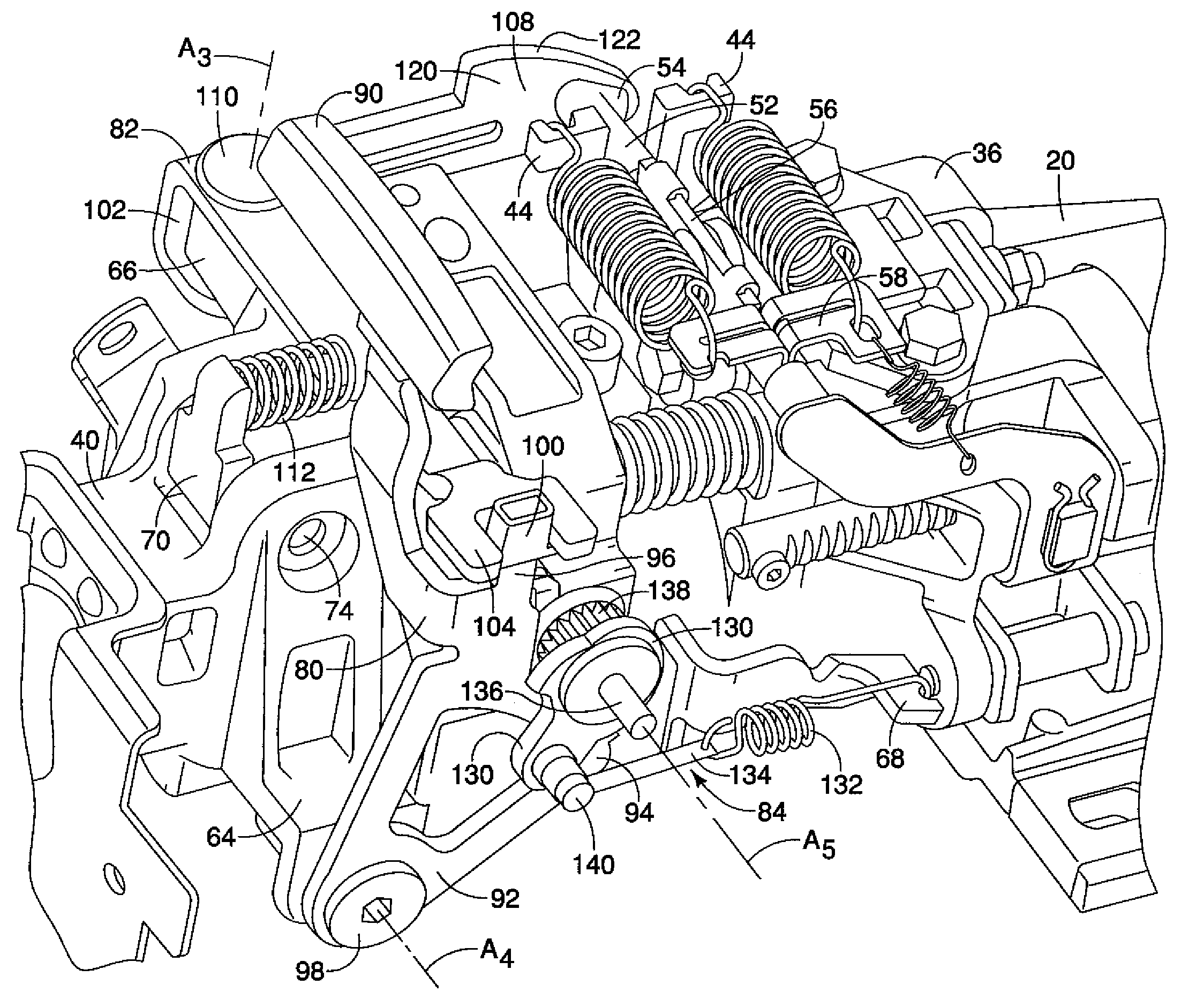
[0093]Referring now to FIG. 21, a portion of a steering column structure 212 having a push rod 252 in accordance with a second embodiment will now be explained. In view of the similarity between the first and second embodiments, the parts of the second embodiment that are identical to the parts of the first embodiment will be given the same reference numerals as the parts of the first embodiment. Moreover, the descriptions of the parts of the second embodiment that are identical to the parts of the first embodiment may be omitted for the sake of brevity.
[0094]The steering column structure 212 of the second embodiment is identical in all ways to the steering column structure 12 of the first embodiment except that the push rod 52 of the first embodiment has been replaced with the push rod 252. The push rod 252 is identical to the push rod 52 of the first embodiment except that the contact section 54 has been replaced with contact section 254. The contact section 254 has an overall arc...
third embodiment
[0095]Referring now to FIG. 22, a portion of a steering column structure 312 having a push rod 352 in accordance with a third embodiment will now be explained. In view of the similarity between the first and third embodiments, the parts of the third embodiment that are identical to the parts of the first embodiment will be given the same reference numerals as the parts of the first embodiment. Moreover, the descriptions of the parts of the third embodiment that are identical to the parts of the first embodiment may be omitted for the sake of brevity.
[0096]The steering column structure 312 of the third embodiment is identical in all ways to the steering column structure 12 of the first embodiment except that the push rod 52 of the first embodiment has been replaced with the push rod 352. The push rod 352 is identical to the push rod 52 of the first embodiment except that the contact section 54 has been replaced with contact section 354. The contact section 354 has an overall arcuate ...
fourth embodiment
[0097]Referring now to FIG. 23, a portion of a steering column structure 412 having a push rod 452 in accordance with a fourth embodiment will now be explained. In view of the similarity between the first and fourth embodiments, the parts of the fourth embodiment that are identical to the parts of the first embodiment will be given the same reference numerals as the parts of the first embodiment. Moreover, the descriptions of the parts of the fourth embodiment that are identical to the parts of the first embodiment may be omitted for the sake of brevity.
[0098]The steering column structure 412 of the fourth embodiment is identical in all ways to the steering column structure 12 of the first embodiment except that the push rod 52 of the first embodiment has been replaced with the push rod 452. The push rod 452 is identical to the push rod 52 of the first embodiment except that the contact section 54 has been replaced with contact section 454. The contact section 454 extends in a direc...
PUM
 Abstract
Description
Claims
Application Information
 - R&D
- Intellectual Property
- Life Sciences
- Materials
- Tech Scout
- Unparalleled Data Quality
- Higher Quality Content
- 60% Fewer Hallucinations
Browse by: Latest US Patents, China's latest patents, Technical Efficacy Thesaurus, Application Domain, Technology Topic, Popular Technical Reports.
© 2025 PatSnap. All rights reserved.Legal|Privacy policy|Modern Slavery Act Transparency Statement|Sitemap|About US| Contact US: help@patsnap.com


