Floating disc type oil sucking device for oil-containing sewage tank

A technology of oily sewage and floating discs, which is applied in the direction of grease/oily substance/floating matter removal devices, water/sludge/sewage treatment, water pollutants, etc., and can solve the problems of inability to effectively remove oil layers, difficulty in accurately controlling distance, and oil absorption efficiency low cost, low cost, easy installation and disassembly, and reduced operating costs

Inactive Publication Date: 2015-04-08
HANGZHOU FURUDE TECH
View PDF4 Cites 8 Cited by
  • Summary
  • Abstract
  • Description
  • Claims
  • Application Information

AI Technical Summary

Problems solved by technology

However, this method needs to grasp the right timing to prevent the oil layer from missing the overflow hole. At the same time, it is necessary to control the flow rate at the upstream inlet of the oily sewage tank to be smaller than the flow rate at the overflow port, and configure many tanks and regulating devices downstream. The operation is very difficult and feasible. lower
If the method of manually controlling the oil discharge is adopted, it is difficult for the operator to accurately control the distance between the oil suction port and the oil-water interface. If the distance is too large, air suction will easily occur. If the oil suction port goes deep below the interface, it will mainly suck the oil from the lower layer. Water, low oil absorption efficiency, unable to effectively remove the oil layer

Method used


Image

  • Floating disc type oil sucking device for oil-containing sewage tank

Examples


Embodiment 1

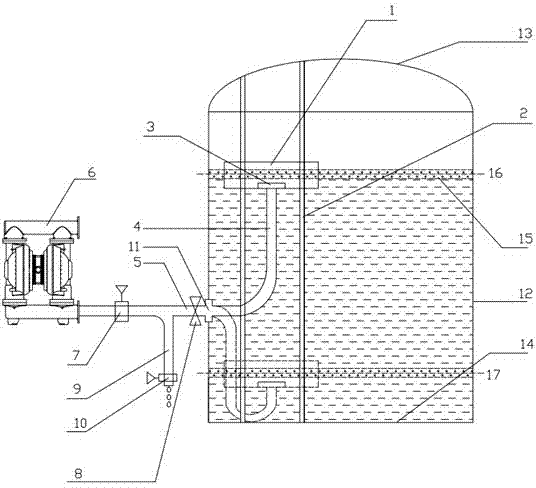
[0026] Such as figure 1 As shown, the standard suction lift of the air diaphragm pump 6 is 6.5m, and the geometric center of the pump suction port 11 is located at 1 / 3 of the height of the oily sewage tank 12 .

[0027] When the height of the oil-water interface 15 is in the state of the high liquid level 16, the shut-off valve 8 is opened. And, close the stop valve 7, open the pipe valve 10, and use the overflow method to drain the oil, so that the oil layer is driven by gravity to flow through the external jumper 9 and be discharged out of the tank.

[0028] When the oil reservoir at the oil-water interface 15 is substantially emptied, and the discharged liquid is mostly water, the shut-off valve 8 is closed to terminate this oil suction operation.

Embodiment 2

[0030] Such as figure 1 As shown, the standard suction lift of the air diaphragm pump 6 is 7.5m, and the geometric center of the pump suction port 11 is located at 1 / 3 of the height of the oily sewage tank 12 .

[0031] When the height of the oil-water interface 15 is in the state of the low liquid level 17, the shut-off valve 8 is opened. And, open the shut-off valve 7, close the pipe valve 10, turn on the air diaphragm pump 6, and adopt the method of vacuuming, so that the oil layer flows through the oil discharge pipeline 5 and is discharged out of the tank.

[0032] When the oil reservoir at the oil-water interface 15 is substantially emptied, and the discharged liquid is mostly water, the shut-off valve 8 is closed to terminate this oil suction operation.


PUM


Abstract

The invention discloses a floating disc type oil sucking device for an oil-containing sewage tank. The floating disc type oil sucking device comprises an oil collecting component and an oil-water separation component, wherein the oil-water separation component mainly consists of a floating disc, two guide rods and an oil sucking hose; two guide rods are mounted between the vault and the bottom of the oil-containing sewage tank; two sides of the floating disc are connected with the two guide rods in a sliding manner; an oil sucking hole is positioned right below the floating disc and is connected with the bottom of the floating disc; one end of the oil sucking hose is connected with the oil sucking hole; the other end of the oil sucking hose is connected with a pumping inlet in the side surface of the oil-containing sewage tank; the pumping inlet is connected with the oil-containing component outside the tank. When the liquid level inside the tank is higher than the horizontal height of an air diagram pump, a check valve is closed, a tube valve is opened, and oil is discharged by using an overflowing method; when the liquid level is lower than the horizontal height of the air diagram pump, the check valve is opened, the tube valve is closed, the air diagram pump is started, and thus oil is discharged in a vacuuming manner. By adopting the floating disc type oil sucking device, the time and resource waste caused by situation that the tank is opened to clean out oil layers at regular time is avoided, and the operation cost of the device is effectively lowered; the floating disc type oil sucking device is easy to mount and dismount.

Description

technical field [0001] The invention relates to an oil absorbing device for an oily sewage tank, in particular to a floating disc type oil absorbing device for an oily sewage tank. Background technique [0002] Oil refining, petrochemical, coking, steel and other industries will produce oily sewage during production and processing, which is usually stored in oily sewage tanks. After the oily sewage is left standing in the tank, due to the difference in density, stratification will occur, in which oil, gas and oil are located in the upper layer, and water is located in the lower layer, forming an oil-water interface. Due to the position of the water outlet, the oil in the upper layer will stay in the tank for a long time, and if it is not repaired and cleaned in time, it is easy to accumulate. During the operation of the sewage tank, oil and gas encounter an open flame or ignite with ferrous sulfide, causing co...

Claims


Application Information

Patent Timeline
Patent Type & Authority Applications(China)
IPC IPC(8): C02F1/40
CPCC02F1/40C02F2101/32
Inventor 偶国富朱吉新郑智剑金浩哲
Owner HANGZHOU FURUDE TECH
Why Eureka
Try Eureka