Seismic horizon automatic extraction device and method based on dynamic planning

A dynamic programming and automatic extraction technology, applied in seismic signal processing and other directions, can solve problems such as high computational cost, inability to reveal geological structure information, and inability to automatically extract accurate seismic horizons with consistent phases, reducing computational costs, time saving effect

Inactive Publication Date: 2020-05-15
UNIV OF SCI & TECH OF CHINA
View PDF8 Cites 0 Cited by
  • Summary
  • Abstract
  • Description
  • Claims
  • Application Information

AI Technical Summary

Problems solved by technology

[0008] 1. In areas where events are discontinuous in seismic data (for example, faults, noise, etc.), traditional methods cannot automatically extract accurate seismic horizons with consistent phases;
[0009] 2. Traditional methods often extract over-smooth seismic horizons, which cannot reveal detailed geological structure information;
[0010] 3. Traditional methods require high computational costs and cannot meet the current needs for efficient interpretation of seismic data in oil and gas exploration and development

Method used


Image

  • Seismic horizon automatic extraction device and method based on dynamic planning
  • Seismic horizon automatic extraction device and method based on dynamic planning
  • Seismic horizon automatic extraction device and method based on dynamic planning

Examples


Embodiment 1

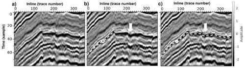
[0072] Such as image 3 Shown are horizons extracted from 2D seismic images using the slope-based method and using the dynamic programming method, respectively. image 3 (a) is the input original 2D seismic image; image 3 The white dotted line in (b) is the horizon picked up by the traditional slope-based method; image 3 The white dotted line in (c) is the horizon picked up by the method of dynamic programming in the present invention. It can be seen that the position of the white arrow has been significantly improved, image 3 The result in (c) is more accurate.

Embodiment 2

[0074] Such as Figure 4 Shown is the comparison chart between the results of this method and manual interpretation. in, Figure 4 (a) shows the actual 3D seismic image of a certain area, and the white arrow shows the target horizon (indicating the position of the black trough); Figure 4 (b) It is the result of manual interpretation, the phase jump phenomenon of the horizon is very obvious, and there are obvious grid-like artifacts; Figure 4 (c) as a result of the present invention, with Figure 4 (b) is the initial horizon, the result after updating by dynamic programming. It can be seen that the phases of the planes picked up by the dynamic programming method are more consistent (basically all black), and the grid-like artifacts are also eliminated.

Embodiment 3

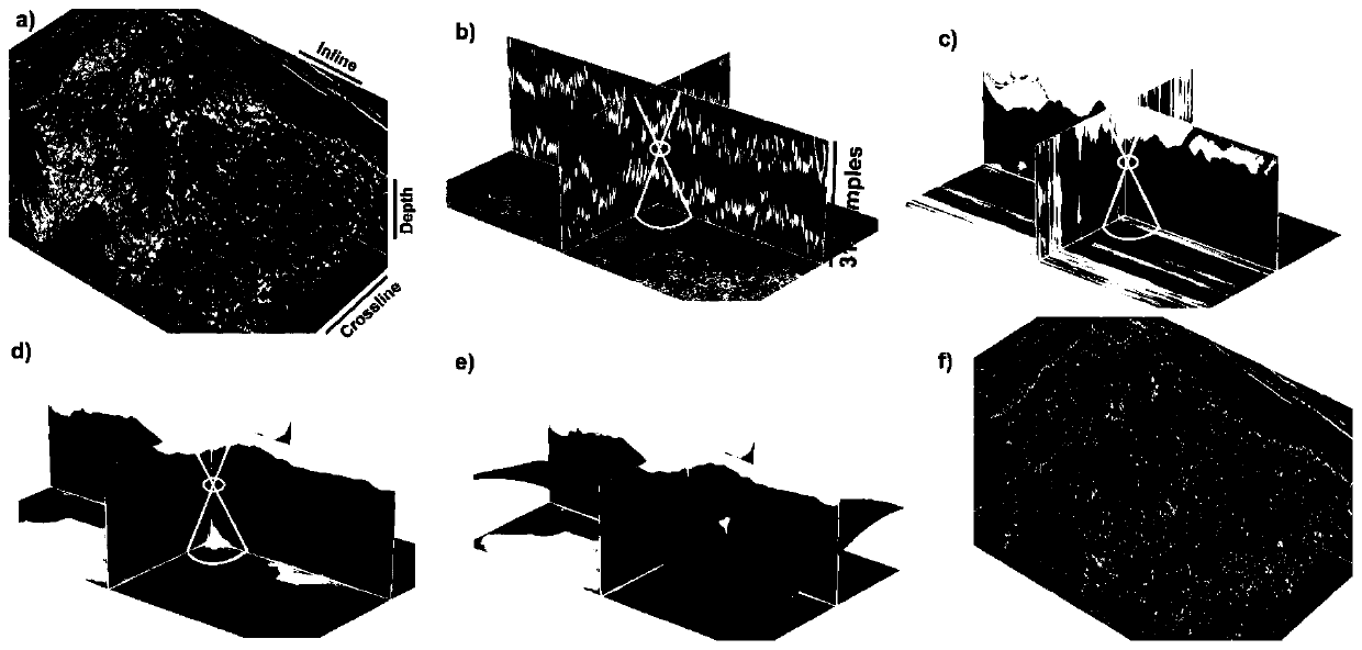
[0076] Such as Figure 5 As shown, among them, Figure 5 (a) is the input original 3D seismic image, and the white arrow indicates the target layer (white peak position); Figure 5 (b) is the result obtained by the slope-based method; Figure 5 (c) is the result obtained by the present invention. As can be seen, Figure 5 The horizons in (c) have more consistent phases, and more detailed geological structures can be obtained, such as the channel information indicated by the white arrow. Figure 6 for from Figure 5 The comparison results of the 2D profiles: where Figure 6 (b) for Figure 6 In the area shown by the black box in (a), it can be clearly seen that the result obtained based on the method of the present invention (black dotted line) is significantly better than the result obtained by the slope-based method (white solid line).


PUM


Abstract

A seismic horizon automatic extraction method based on dynamic programming is characterized by comprising the following steps: step 1, obtaining an initial horizon near a target seismic horizon to besolved; step 2, taking the initial horizon as a center, selecting a window with a proper size, and selecting a small area containing a target horizon; step 3, according to the initial horizon, flattening the image of the selected small area; step 4, searching a global optimal path in the small area by using a dynamic planning method; and step 5, inversely transforming the obtained optimal path into an initial coordinate space to obtain an optimized target seismic horizon of the required solution. According to the method, the correct seismic horizon can be effectively picked up, and even the seismic horizon with the consistent phase can still be accurately and automatically tracked in a complex discontinuous area in seismic data. Detailed geological structure information can be well revealed, the calculation cost can be greatly reduced, and time is saved.

Description

technical field [0001] The invention relates to seismic data analysis in seismic data interpretation, in particular to extracting seismic horizons from seismic images. Background technique [0002] Extracting seismic horizons is a fundamental step in seismic interpretation. Seismic horizons are considered strata that match constant geological ages, represent geologically synchronous surfaces, and are also important for identifying structural and stratigraphic features. In addition, people also use horizons to analyze the ancient sedimentary environment and landform characteristics. [0003] In the initial earthquake interpretation, people mainly relied on manual interpretation, which required a lot of labor and time. In the face of huge seismic data and complex geological structures, manual interpretation will lead to low efficiency, so people have proposed different automatic or semi-automatic methods for picking seismic horizons, but these methods also have different prob...

Claims


Application Information

Patent Timeline
Patent Type & Authority Applications(China)
IPC IPC(8): G01V1/28G01V1/30
CPCG01V1/28G01V1/30
Inventor 伍新明闫上升
Owner UNIV OF SCI & TECH OF CHINA
Why Eureka
Try Eureka