
A system for autonomously tracking sun rays and its control method

A sun ray and control method technology, which is applied in the system of autonomously tracking the sun ray and its control field, can solve the problems that non-professionals cannot operate casually, the circuit technical equipment is complicated, and it is inconvenient to move or assemble and disassemble, so as to achieve the maximum absorption efficiency Minimize, reduce cost, control simple effects

Active Publication Date: 2020-05-29
FUJIAN LYUHUA ENERGY INVESTMENT CO LTD
View PDF11 Cites 0 Cited by
  • Summary
  • Abstract
  • Description
  • Claims
  • Application Information

AI Technical Summary

Problems solved by technology

Its deficiencies are: 1. It adopts computer data theory, which requires the data and settings of the latitude and longitude of the earth. Once installed, it is inconvenient to move or assemble and disassemble. It is necessary to recalculate parameters, set data and settings after each movement. Adjust various parameters; 2. The principle, circuit, technology, and equipment are very complicated, and the solar tracking system cannot be operated casually by non-professionals; 3. The existing solar absorbing device tracking system mainly relies on external input signals to control solar energy absorption The device tracks the sun's rays; most of its power system uses electric energy to convert into kinetic energy; overheating of the solar absorbing device will affect its power generation; 4. High cost

Method used


Image

  • A system for autonomously tracking sun rays and its control method
  • A system for autonomously tracking sun rays and its control method
  • A system for autonomously tracking sun rays and its control method

Examples


Embodiment Construction

[0033] The present invention will be described in detail below in conjunction with the accompanying drawings and specific embodiments.

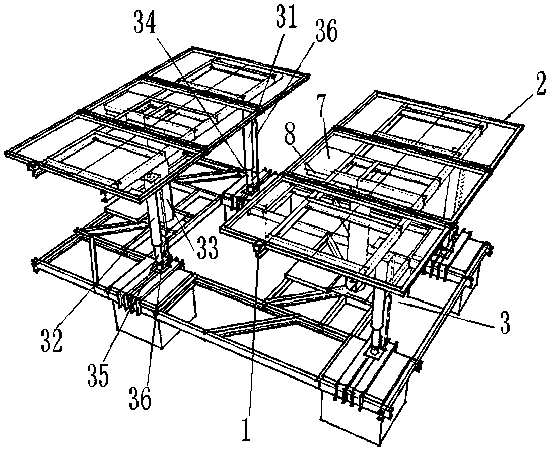
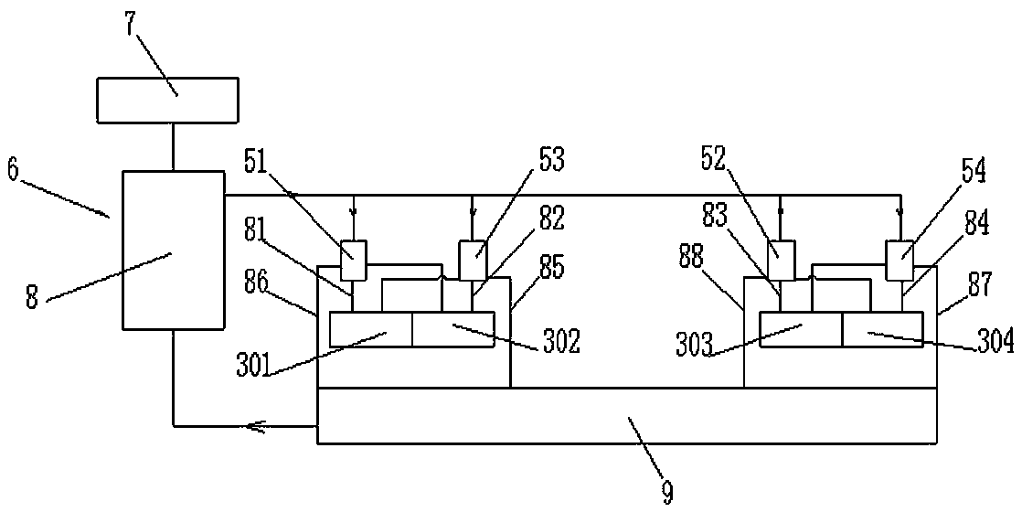
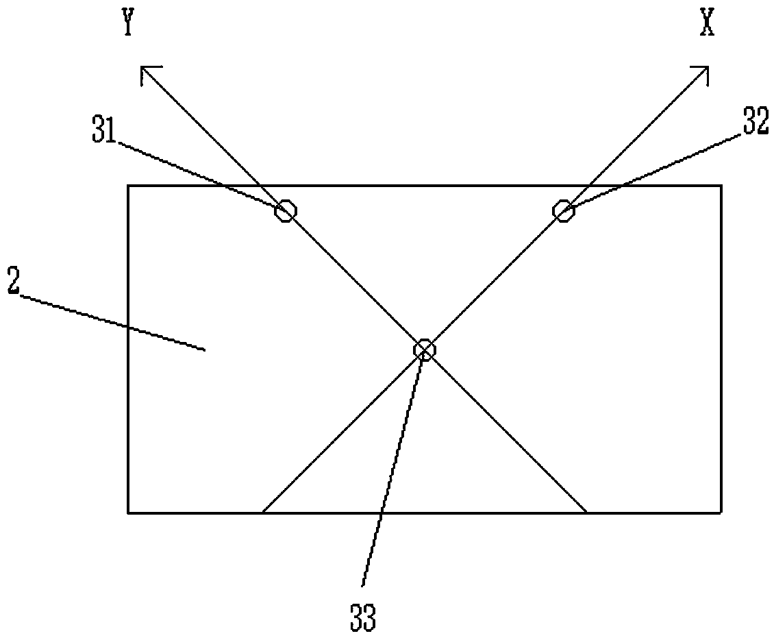
[0034] see Figure 1-5, a system for autonomously tracking sunlight, including a light control valve 1, a photovoltaic panel 2, and at least three columns 3 arranged below the photovoltaic panel 2, the upper end of the column 3 is ball-connected with the lower surface of the photovoltaic panel 2, and the three columns 3 are the first A vertical rod 31, a second vertical rod 32 and a third vertical rod 33; the lower end of the third vertical rod 33 is fixedly connected to a substrate, and the lower ends of the first vertical rod 31 and the second vertical rod 32 are ball-connected to the substrate; the substrate can be floating On the water surface, it can also be fixed on land, such as roadside or roof; the first upright 31, the second upright 32 and the third upright 33 are arranged in a triangle; the first upright 31 and the second upright ...


PUM


Abstract

The invention relates to a system for autonomously tracking sunlight and a control method thereof. The system is composed of a light-operated valve, a photovoltaic panel, and at least three standing posts arranged below the photovoltaic panel; and the upper ends of the standing posts and the lower surface of the photovoltaic panel are in ball connection. The three standing posts include a first standing post, a second standing post, and a third standing post; the lower end of the third standing post is fixedly connected with a substrate; the lower ends of the first standing post and the second standing post are in ball connection with the substrate; and the first standing post, the second standing post, and the third standing post are distributed in a triangular manner. A first hydraulic cylinder and a second hydraulic cylinder are arranged inside the first standing post and the second standing post; the axial lengths of the first standing post and a second adjustable standing post are changed by hydraulic pressure pushing; and vertical reset springs are arranged at the first standing post and the second standing post. The light-operated valve includes a condensation device, wherein the condensation device and the photovoltaic panel are located on the same plane; and the condensation device includes at least one convex lens; and an annular thermal-expansion working-medium valve body is arranged at the lower surface of the condensation device.

Description

technical field [0001] The invention relates to a system for autonomously tracking solar rays and a control method thereof, belonging to the field of solar energy absorbing equipment. Background technique [0002] Solar photovoltaic power generation is a very promising renewable clean energy, and it is also considered to be the most advantageous renewable energy, which has achieved rapid development in recent years. How to maximize the solar energy absorption efficiency is a problem that needs to be solved urgently. Due to the rotation of the earth, compared with a solar photovoltaic power generation system at a fixed location, the sun rises and sets every day in spring, summer, autumn and winter. The sun, the power generation efficiency will reach the best state. At present, the general solar tracking system in the world needs to calculate the angle of the sun at different times of each day of the year according to the longitude and latitude of the placement point, and st...

Claims


Application Information

Patent Timeline
Patent Type & Authority Patents(China)
IPC IPC(8): G05D3/12H02S20/32F15B1/027
CPCF15B1/0275G05D3/12H02S20/32Y02E10/50
Inventor 罗仁山郭其秀周辉陈裕炳黄嘉诚刘立腾
Owner FUJIAN LYUHUA ENERGY INVESTMENT CO LTD
Learn More