Transmitting trace-specific information in a transformed application

Inactive Publication Date: 2010-08-10
INTEL CORP
View PDF11 Cites 1 Cited by
  • Summary
  • Abstract
  • Description
  • Claims
  • Application Information

AI Technical Summary

Problems solved by technology

However, not all data transmitted from stage to stage may be necessary.
As a result, unnecessary overhead is incurred in transmitting data that are not needed.
Accordingly, excessive data transmission can negatively impact performance of multi-threaded applications.

Method used


Image

  • Transmitting trace-specific information in a transformed application
  • Transmitting trace-specific information in a transformed application
  • Transmitting trace-specific information in a transformed application

Examples


Embodiment Construction

[0017]In various embodiments, a software program may be compiled to transform the program into a plurality of stages to provide for efficient execution of the program via multiple processing units, for example, independent cores of a processor, individual processors, microengines of a network processor or the like. In different implementations, a compiler or other software tool may be used to analyze an original application and partition it in an appropriate manner to improve pipelining performance. Furthermore, in some implementations an amount of data to be transmitted between upstream and downstream stages of the partitioned program may be minimized. Accordingly, multi-threaded operation may be improved as synchronizations between different threads may be minimized.

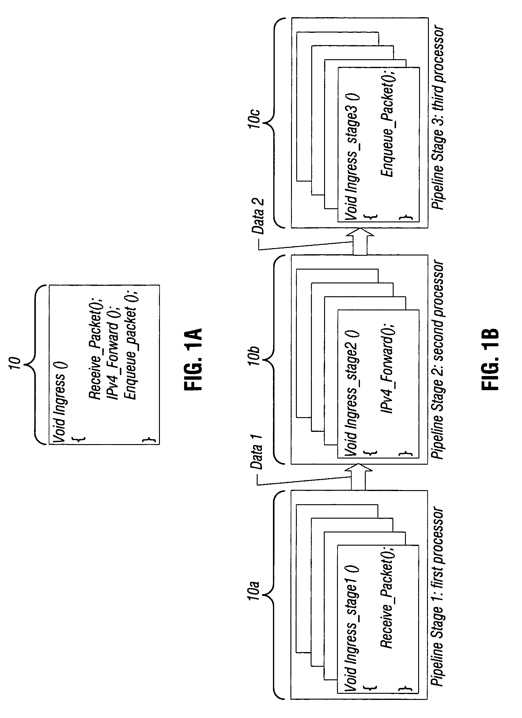
[0018]FIG. 1A shows an example of an application 10 that may be pipelined and parallelized in accordance with an embodiment of the present invention. This example depicts an exemplary ingress operation for a networking...


PUM


Abstract

In one embodiment, the present invention includes a method for partitioning a program segment into at least a first stage and a second stage, determining a live set of variables and control flow information alive at a boundary between the first and second stages, and controlling the first stage to transmit a trace-specific portion of the live set for a first trace to the second stage via a communication channel. In such manner, reduced transmission of data between the stages is effected. Other embodiments are described and claimed.

Description

BACKGROUND[0001]Embodiments of the present invention relate to data processing and more particularly to optimizing software applications.[0002]Advances in processor technology have spawned the development of network processors (NPs), which are designed specifically to meet the requirements of next generation network equipment. In order to address the unique challenges of network processing at high speeds (e.g., the latency for a single external memory access in a NP is usually larger than the worst-case service time), modem network processors generally have a highly parallel multi-processor architecture. For instance, some network processors process packets in a microengine cluster that includes multiple microengines. Each microengine is a programmable processor to perform various activities, for example, packet processing. To process packets at high speeds, multiple microengines may run in parallel, each supporting multiple hardware threads.[0003]Some processors such as network pro...

Claims


Application Information

Patent Timeline
IPC IPC(8): G06F9/45
CPCG06F8/456
Inventor JIANG, XIAODANDAI, JINQUAN
Owner INTEL CORP
Why Eureka
Try Eureka