Disk loading apparatus

a technology of chucking operation and chucking position, which is applied in the direction of magnetic recording, data recording, instruments, etc., can solve the problems of not being able to improve the stability of the centering operation at low cost, the above-described problem is more likely to occur when using small-diameter disks, and the failure to accurately load the disk onto the chucking position, etc., to achieve the improvement of the stability of the chucking operation after loading, the stability of th

Inactive Publication Date: 2010-08-10
FUNAI ELECTRIC CO LTD
View PDF15 Cites 2 Cited by
  • Summary
  • Abstract
  • Description
  • Claims
  • Application Information

AI Technical Summary

Benefits of technology

[0018]The present invention has been made in consideration of the above-described problems and circumstances, and an object thereof is to provide a disk loading apparatus capable of improving the stability in the centering operation at low cost only by changing the shape of the guide groove without adding extra parts or complicated structures while directly employing the basic structure of the disk loading apparatus described with reference to FIGS. 9 and 10.
[0021]In accordance with the thus arranged disk loading apparatus, when a disk inserted through the slot is drawn by the normal rotation of the feed roller and received by the disk arm in the initial position at a biased position, the drawing action of the feed roller causes the disk to push a biased portion of the disk arm and thereby the disk arm is subject to a torque around the engaging body. This causes the disk arm to be tilted from the neutral state so that the locking parts in the engaging body are pressed against the slant wall surfaces of the initial part in the guide groove. When the engaging body is thus pressed against the slant wall surfaces in the guide groove, the locking parts are kept locked against the slant wall surfaces so that the disk arm is not retracted or the sliding resistance of the engaging body increases prominently, even if the drawing action of the feed roller may cause the disk to push the disk arm in the retracting direction. As a result, the pressing state between the disk that is given a force in the drawing direction by the feed roller and the disk arm appears normally and therefore the centering function of the feed roller can also be exhibited normally and stably. Meanwhile, when the disk is centered by the centering function of the feed roller, the disk arm returns to the neutral state and the locking parts in the engaging body are released from the slant wall surfaces, so that the disk arm starts to be retracted by the push-in operation of the disk that is given a feed force by the feed roller and the disk is drawn onto the chucking position accurately.
[0022]The present invention also employs an arrangement that receiving surfaces adapted to come into contact with the engaging body to limit the tilt angle of the disk arm when the disk arm is tilted from the neutral state with the engaging body are provided continuously from the slant wall surfaces, which exhibits a particularly preferable effect as described below. That is, the feeding function and centering function of the feed roller are exhibited more effectively as the width of a portion of the feed roller that faces the disk (hereinafter referred to as “contact width”) increases. Also, since the disk has a circular shape, the contact width of the feed roller against the disk increases as the contact portion of the feed roller against the disk comes closer to the center of the disk. Hence, if the engaging body is adapted to come into contact with the receiving surfaces so that the tilt angle of the disk arm is limited as in the present invention, the tilt angle of the disk arm can be kept small so that the amount of drawing of the disk is reduced when the disk that is drawn by the feed roller is received at a biased portion of the disk arm. Therefore, the feeding function and centering function of the feed roller can be exhibited effectively by increasing the contact width of the feed roller against the disk.
[0023]The present invention may employ an arrangement that in the guide groove, the groove width of the initial part is greater than that of the principal part, the slant wall surfaces are provided at the juncture between the principal part and the initial part, and the groove wall surfaces in the initial part that run parallel to the groove wall surfaces in the principal part are formed as the receiving surfaces. Employing this arrangement allows the slant wall surfaces and the receiving surfaces to be included easily in the guide groove.
[0026]As described heretofore, in accordance with the present invention, the stability in the centering operation can be improved at low cost only by mainly changing the shape of the guide groove without adding extra parts or complicated structures while directly employing the basic structure of the disk loading apparatus described with reference to FIGS. 9 and 10. This allows the loading performance of disk loading apparatuses capable of using both large-diameter disks and small-diameter disks separately, and therefore, the stability in the chucking operation after loading to be improved. Accordingly, if such a disk loading apparatus is applied in, for example, DVD players or DVD recorders, users can enjoy stable images and also there is no possibility that faulty loading would cause damages to disks.

Problems solved by technology

Therefore, there has been a problem in that even if the feed roller 2 may have a centering function, disks may not be loaded accurately onto the chucking position due to the loss of the stability in the centering operation.
Particularly, in the disk loading apparatus capable of using both large-diameter disks and small-diameter disks separately, since the displacement of small-diameter disks for normal centering is greater than that of large-diameter disks, the above-described problem is more likely to occur when using small-diameter disks.
Hei 8-7433 is achieved by adding extra parts and complicated structures, which cannot improve the stability in the centering operation at low cost.
Also, neither of the techniques proposed in Japanese Patent Laid-Open Publication Nos.

Method used


Image

  • Disk loading apparatus
  • Disk loading apparatus
  • Disk loading apparatus

Examples


Embodiment Construction

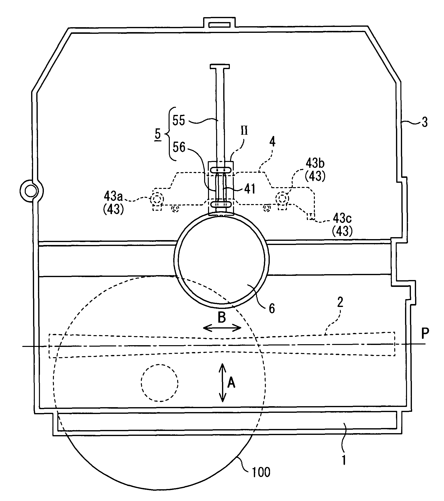
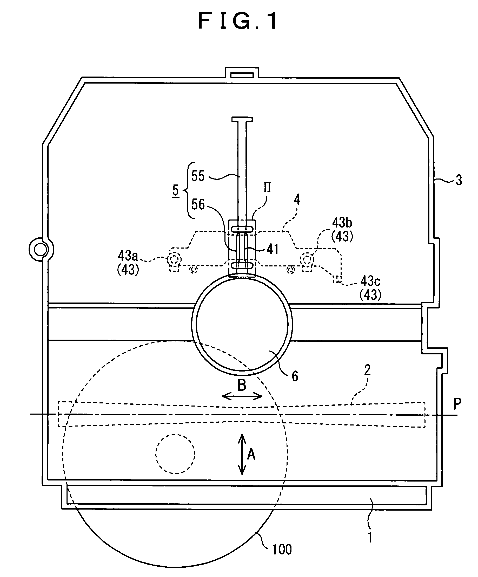
[0040]FIG. 1 is a schematic configuration view at the beginning stage of loading in a disk loading apparatus according to an embodiment of the present invention.

[0041]The basic configuration of the disk loading apparatus shown in FIG. 1 is the same as that of the disk loading apparatus described with reference to FIG. 9, etc. That is, in this disk loading apparatus, the normal rotation of a feed roller 2 that is installed in the vicinity of a slot 1 draws a disk 100 onto a chucking position, while the reverse rotation of the feed roller 2 feeds the disk 100 out of the chucking position to eject through the slot 1. The arrow A indicates the drawing and ejecting direction. Also, the feed roller 2 is formed in an hourglass shape with a diameter increasing from the center thereof in the axial direction. The feed roller 2 is adapted to rotate in contact with one surface of the disk 100 to fulfill a centering function of moving the disk 100 toward the center in the axial direction, i.e., ...


PUM

PropertyMeasurementUnit
diameteraaaaaaaaaa
diameteraaaaaaaaaa
feed forceaaaaaaaaaa

Abstract

There is provided a disk loading apparatus capable of improving the stability in the centering operation at low cost only by changing the shape of the guide groove without adding extra parts or complicated structures. The disk loading apparatus includes a feed roller 2, a disk arm 4 adapted to move back and forth between an initial position where a disk 100 that is drawn by the feed roller 2 is received and a retracted position that corresponds to a chucking position for the disk, and a guide groove 5. The feed roller 2 has a function of centering the disk 100. The guide groove 5 includes slant wall surfaces 57 with the groove width therebetween decreasing progressively in the retracting direction of the disk arm 4, and receiving surfaces 58 for limiting the tilt angle of the disk arm 4.

Description

BACKGROUND OF THE INVENTION[0001]1. Field of the Invention[0002]The present invention relates to disk loading apparatuses and, in particular, to a slot-in type disk loading apparatus adapted to load a disk inserted through a slot onto a chucking position under the centering action of a feed roller.[0003]2. Description of the Related Art[0004]FIGS. 9 and 10 schematically show the basic configuration of this kind of disk loading apparatus, where FIG. 9 is a schematic configuration view at the beginning stage of loading where a disk 100 is inserted through a slot 1 and FIG. 10 is a schematic configuration view at the termination stage of loading where the disk 100 is loaded and arranged on a chucking position.[0005]In this disk loading apparatus, the normal rotation of a feed roller 2 that is installed in the vicinity of the slot 1 draws the disk 100 inserted through the slot 1 onto the chucking position, while the reverse rotation of the feed roller 2 feeds the disk 100 out of the chu...

Claims


Application Information

Patent Timeline
Patent Type & Authority Patents(United States)
IPC IPC(8): G11B17/04
CPCG11B17/0404G11B17/0515
Inventor SAWAI, KUNIONASU, KAZUMASASAKAGAMI, KATSUYA
Owner FUNAI ELECTRIC CO LTD
Why Eureka
Try Eureka