
Turbocharger control system

a control system and turbocharger technology, applied in the direction of electric control, combustion engines, machines/engines, etc., can solve the problems of inability to achieve optimal engine operation, inability to achieve optimum engine operation, and inability to achieve precision modulation

Active Publication Date: 2010-08-17
CATERPILLAR INC
View PDF36 Cites 32 Cited by
  • Summary
  • Abstract
  • Description
  • Claims
  • Application Information

AI Technical Summary

Problems solved by technology

However, since there is no compensation for operating at different altitudes, the loss of boost at high altitudes and over boost at lower altitudes and ambient temperatures may occur.
Therefore optimum operation of the engine is not achieved.
Wastegate valves have been successful in protecting the engine from excessive boost (peak cylinder pressure) at low altitudes (ambient temperatures) but have not been successfully used in situations where precision modulation of the wastegate valve is required.
State of the art fluid operated wastegate control systems lack the responsiveness and accuracy required for good modulation.

Method used


Image

  • Turbocharger control system
  • Turbocharger control system
  • Turbocharger control system

Examples


Embodiment Construction

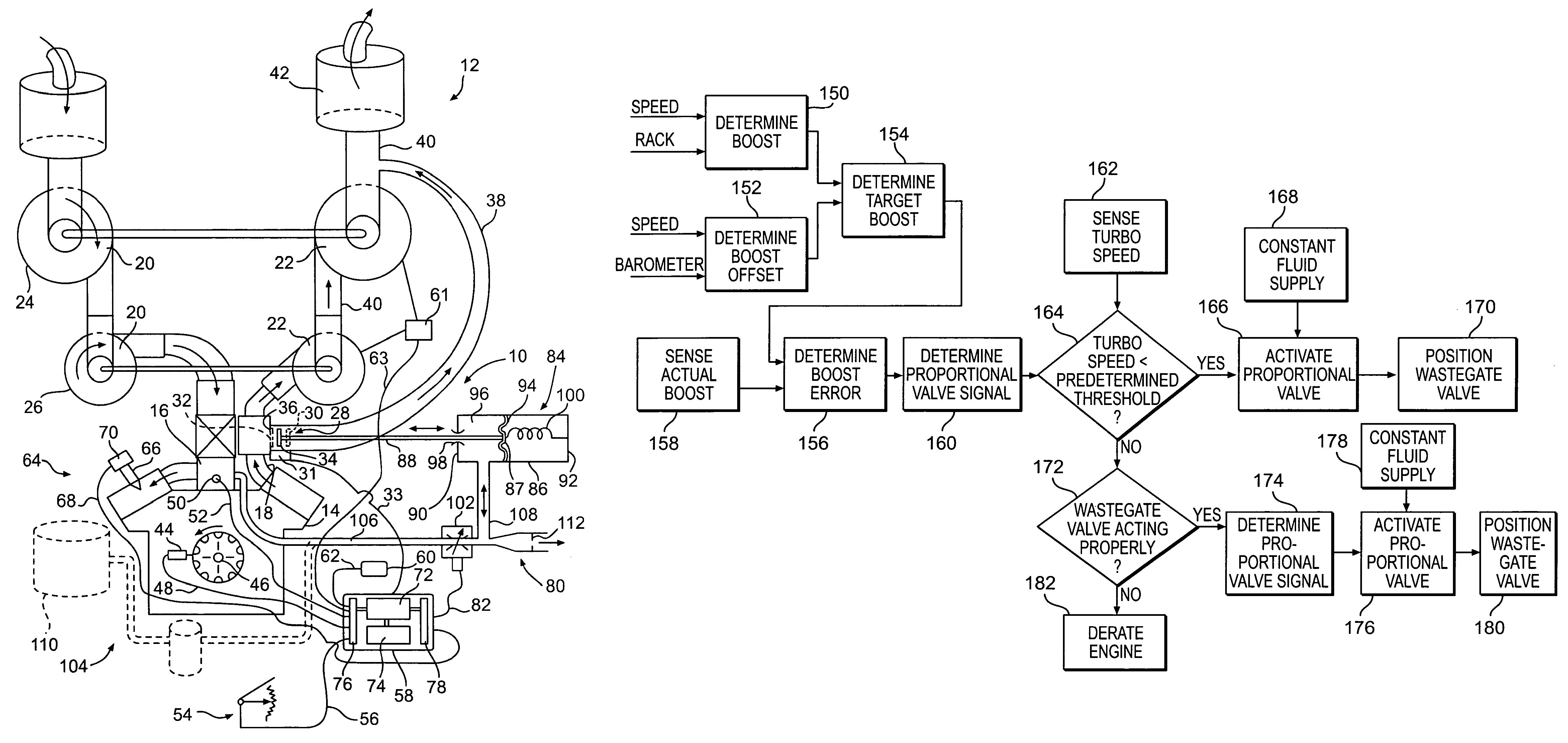
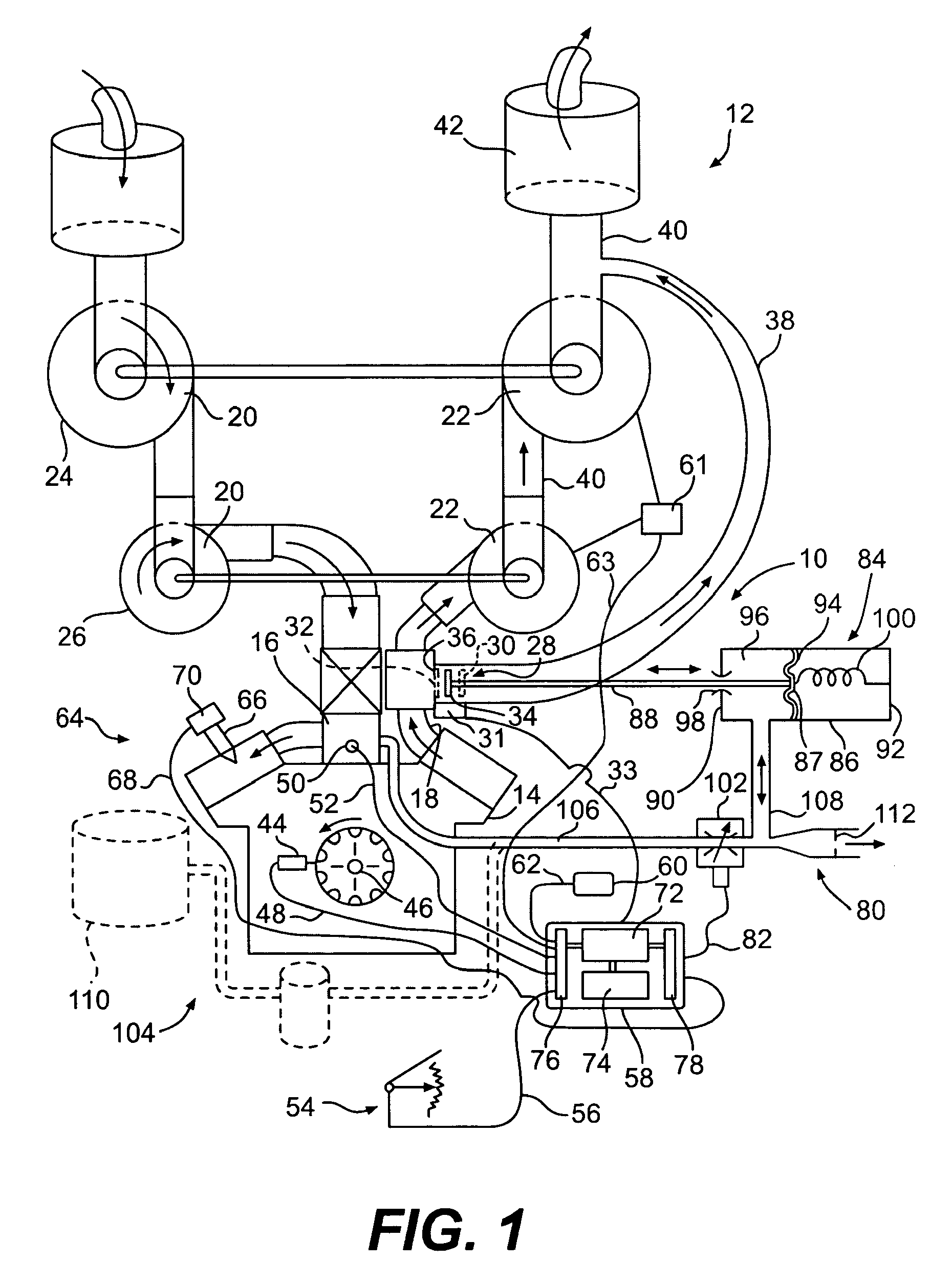
[0015]With reference to the drawings and particularly FIG. 1, a control system 10 for controlling the boost pressure of a turbocharger 12 of an internal combustion engine 14, for example a diesel engine, at various different altitudes is shown. The engine 14 has an intake manifold 16 and an exhaust manifold 18 respectively connected to compressor 20 and turbine 22 sections of the turbocharger 12. The turbocharger 12 of the specific embodiment consists of two turbochargers connected in series, a low pressure turbocharger 24 and a high pressure turbocharger 26 each having a compressor 20 and turbine 22 section. As is well known in the art, in order to cover a full range of engine operating requirements, different altitudes and temperatures affect engine boost requirements, two turbochargers are often provided.

[0016]A wastegate valve 28 connected between the exhaust manifold 18 and the turbine section 22 is movable between an open position 30 at which fluid flow exhausted by the engine...


PUM


Abstract

A system for controlling boost pressure at various different altitudes of operation of a turbo charged internal combustion engine includes a wastegate valve, an actuator, and a controller. Signals delivered from an engine speed sensor, a boost pressure transducer, a barometric pressure sensor, and a turbocharger speed sensor are processed in the controller. A control signal delivered from the controller to the actuator controls the position of the wastegate valve, bypass of exhaust gasses, and the speed of the turbocharger. The controller is configured to compare the turbocharger speed to a predetermined threshold value and determine the control signal based on the comparison.

Description

TECHNICAL FIELD[0001]This disclosure relates to a turbocharger control system and more particularly to a control system for controlling the amount of air delivered by turbocharger to an internal combustion engine at different altitudes of engine operation.BACKGROUND[0002]Turbocharged engines of the type used primarily in off highway trucks often have a pneumatically actuated wastegate valve for controlling the turbocharger speed and thus the boost pressure delivered to the intake manifold of the engine. The wastegate valve is normally disposed in the exhaust system of the engine and controls the speed of the turbocharger by modifying the volume of exhaust gasses directed to the turbine section of the turbocharger.[0003]U.S. Pat. No. 4,697,421 dated Oct. 6, 1987 to Yutaka Otobe et. al. discloses a wastegate valve for bypassing engine exhaust flow from the turbine section and thereby control boost pressure. The wastegate valve is moved by a pneumatic actuator controlled by a control v...

Claims


Application Information

Patent Timeline
Patent Type & Authority Patents(United States)
IPC IPC(8): F02D23/00F02B37/18F02B33/44
CPCF02D23/00F02D41/0007F02D41/221F02B37/013F02B37/18F02B39/16F02D2200/703Y02T10/40Y02T10/144Y02T10/12
Inventor FUNKE, STEVEN J.MUTTI, JAMES H.
Owner CATERPILLAR INC
Learn More