Method for controlling a variable charge air cooler

a variable charge air cooler and control method technology, applied in the direction of electric control, combustion-air/fuel-air treatment, machines/engines, etc., can solve the problems of increased engine misfire potential, loss of torque and engine speed, incomplete combustion,

Inactive Publication Date: 2014-02-20
FORD GLOBAL TECH LLC
View PDF6 Cites 28 Cited by
  • Summary
  • Abstract
  • Description
  • Claims
  • Application Information

AI Technical Summary

Benefits of technology

[0004]In this way, during conditions where condensation is likely to form, intake air flow velocity through the charge air cooler may be increased to break surface tension and prevent the formation of condensation within the charge air cooler. The torque disturbances that may result from the increased intake air velocity may be compensated for by adjusting the throttle and wastegate, maintaining requested torque.

Problems solved by technology

During transient conditions such as hard vehicle acceleration, these water droplets may be blown out of the charge air cooler and into the combustion chambers of the engine resulting in increased potential for engine misfire, loss of torque and engine speed, and incomplete combustion, for example.

Method used


Image

  • Method for controlling a variable charge air cooler
  • Method for controlling a variable charge air cooler
  • Method for controlling a variable charge air cooler

Examples


Embodiment Construction

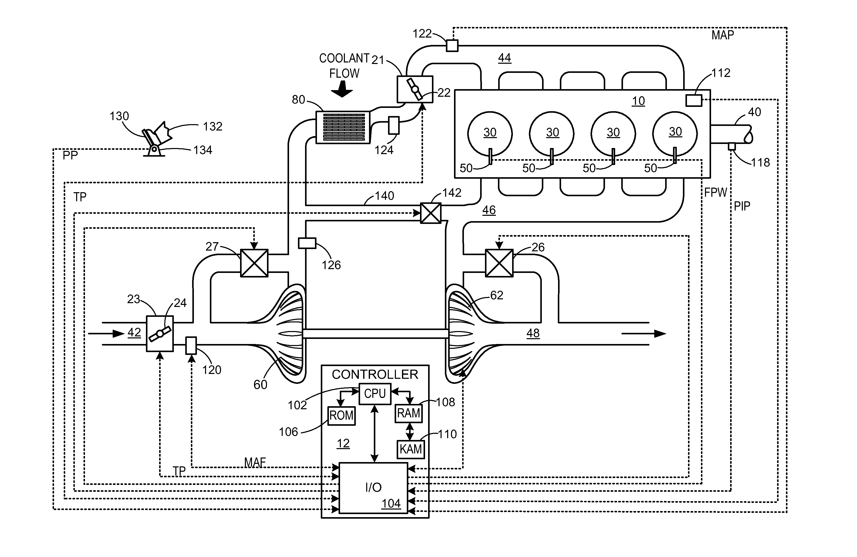
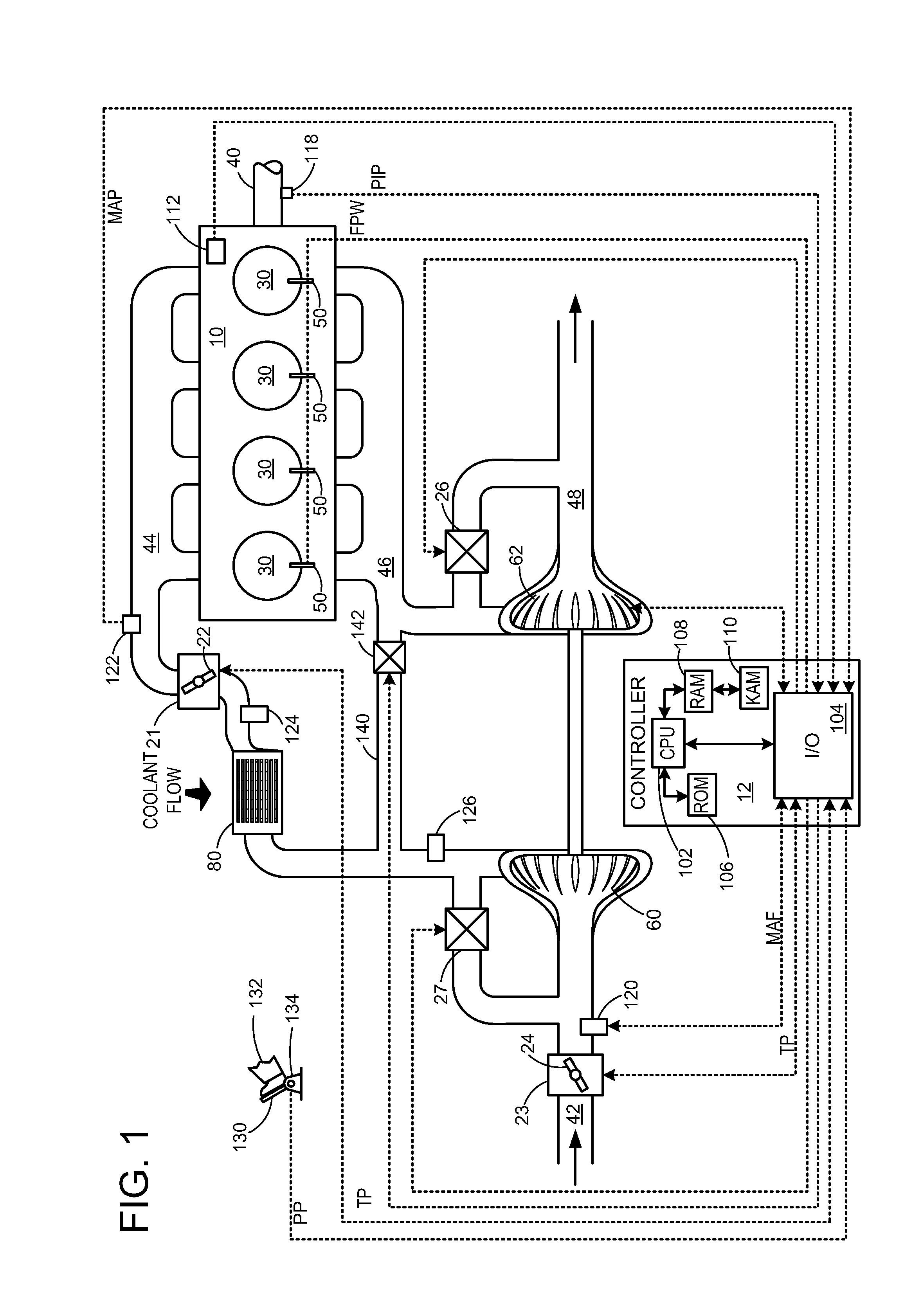
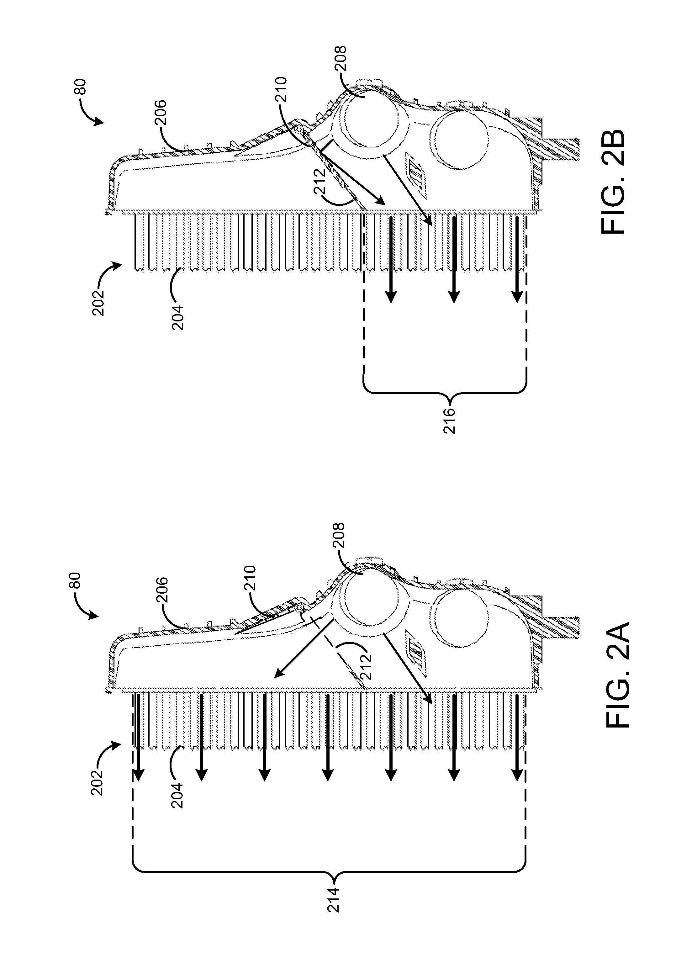
[0016]Condensation formation in a charge air cooler may be detrimental to the engine, as the introduction of the condensate to the cylinders during combustion may cause combustion instability and / or misfire. Further, condensation formation may degrade the charge air cooler, particularly if accumulated condensate freezes during an extended engine-off period. To reduce the accumulation of condensation, a valve positioned in the inlet of the charge air cooler may be closed to selectively route the intake air through a sub-section of the charge air cooler to increase the velocity of the intake air, relative to the velocity of the intake air when it travels through an entirety of the charge air cooler. The valve may be opened or closed in response to a condensation formation value, which provides an estimate of the likelihood that condensation will form within the charge air cooler. Further, to avoid torque disturbances resulting from the adjustment to the valve, the throttle and / or wast...


PUM


Abstract

Embodiments for a charge air cooler are provided. In one example, an engine method comprises increasing intake air flow velocity through a charge air cooler and coordinately adjusting a position of one or more of an intake manifold throttle and a turbocharger wastegate in response to the increased intake air flow velocity to maintain torque. In this way, intake air flow velocity may be increased while maintaining desired torque.

Description

FIELD[0001]The present disclosure relates to an engine including a charge air cooler.BACKGROUND AND SUMMARY[0002]Turbocharged and supercharged engines may be configured to compress ambient air entering the engine in order to increase power. Because compression of the air may cause an increase in air temperature, a charge air cooler may be utilized to cool the heated air thereby increasing its density and further increasing the potential power of the engine. If the humidity of the ambient air is high, however, condensation (e.g., water droplets) may form on internal surfaces of the charge air cooler that are cooler than the dew point of the compressed air. During transient conditions such as hard vehicle acceleration, these water droplets may be blown out of the charge air cooler and into the combustion chambers of the engine resulting in increased potential for engine misfire, loss of torque and engine speed, and incomplete combustion, for example.[0003]The inventors have recognized...

Claims


Application Information

Patent Timeline
Patent Type & Authority Applications(United States)
IPC IPC(8): F02D41/00F02D9/08F02B37/12F02B29/04
CPCF02B29/0418F02B37/18F02D9/02F02D11/10F02D23/00F02D41/0007F02D2009/0272F02D2041/0022F02D2200/0418F02M35/088F02M35/1038F02M35/10393F02M26/05F02M26/10Y02T10/12
Inventor GLUGLA, CHRIS PAULCOCKERILL, CHARLES A.YAMADA, SHUYA SHARKFABIEN, PHIL ANDREWBUCKLAND, JULIA HELEN
Owner FORD GLOBAL TECH LLC
Why Eureka
Try Eureka