
Break-away pedal assembly

a pedal assembly and break-away technology, applied in mechanical control devices, instruments, tractors, etc., can solve the problems of many prior crash management systems that are expensive to repair or replace, and affect the operation of many prior crash management systems

Inactive Publication Date: 2010-08-17
DURA GLOBAL TECH
View PDF21 Cites 14 Cited by
  • Summary
  • Abstract
  • Description
  • Claims
  • Application Information

AI Technical Summary

Problems solved by technology

Operation of many prior crash management systems can be affected by the position of the pedal between its at-rest to fully applied positions.
Additionally, many prior crash management systems are expensive to repair or replace after a collision.

Method used


Image

  • Break-away pedal assembly
  • Break-away pedal assembly
  • Break-away pedal assembly

Examples


Embodiment Construction

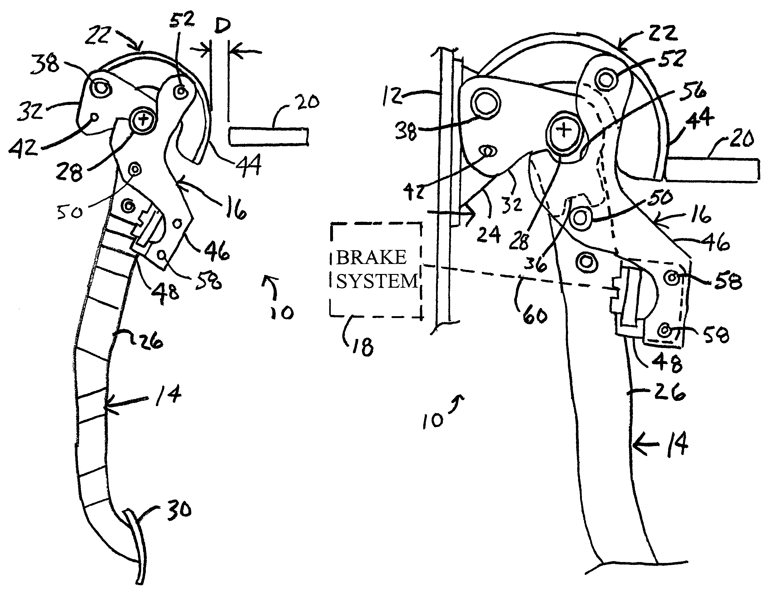
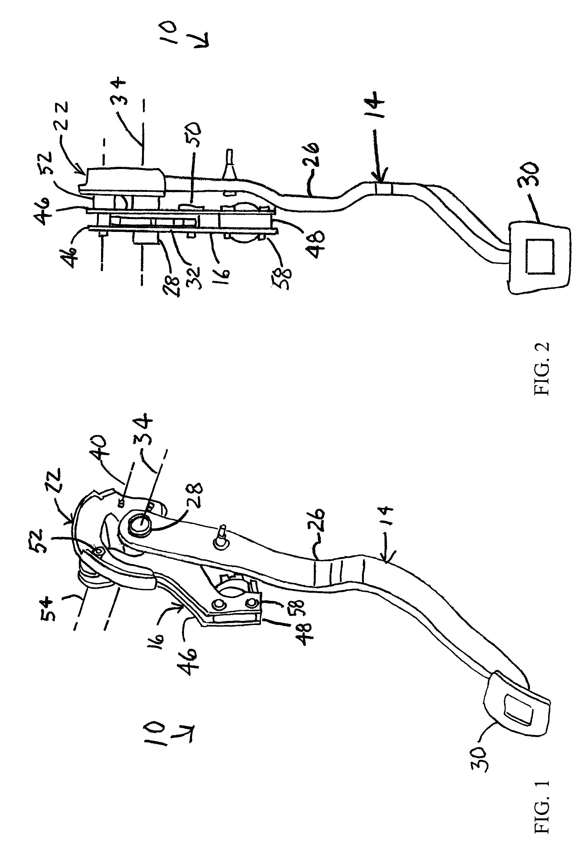
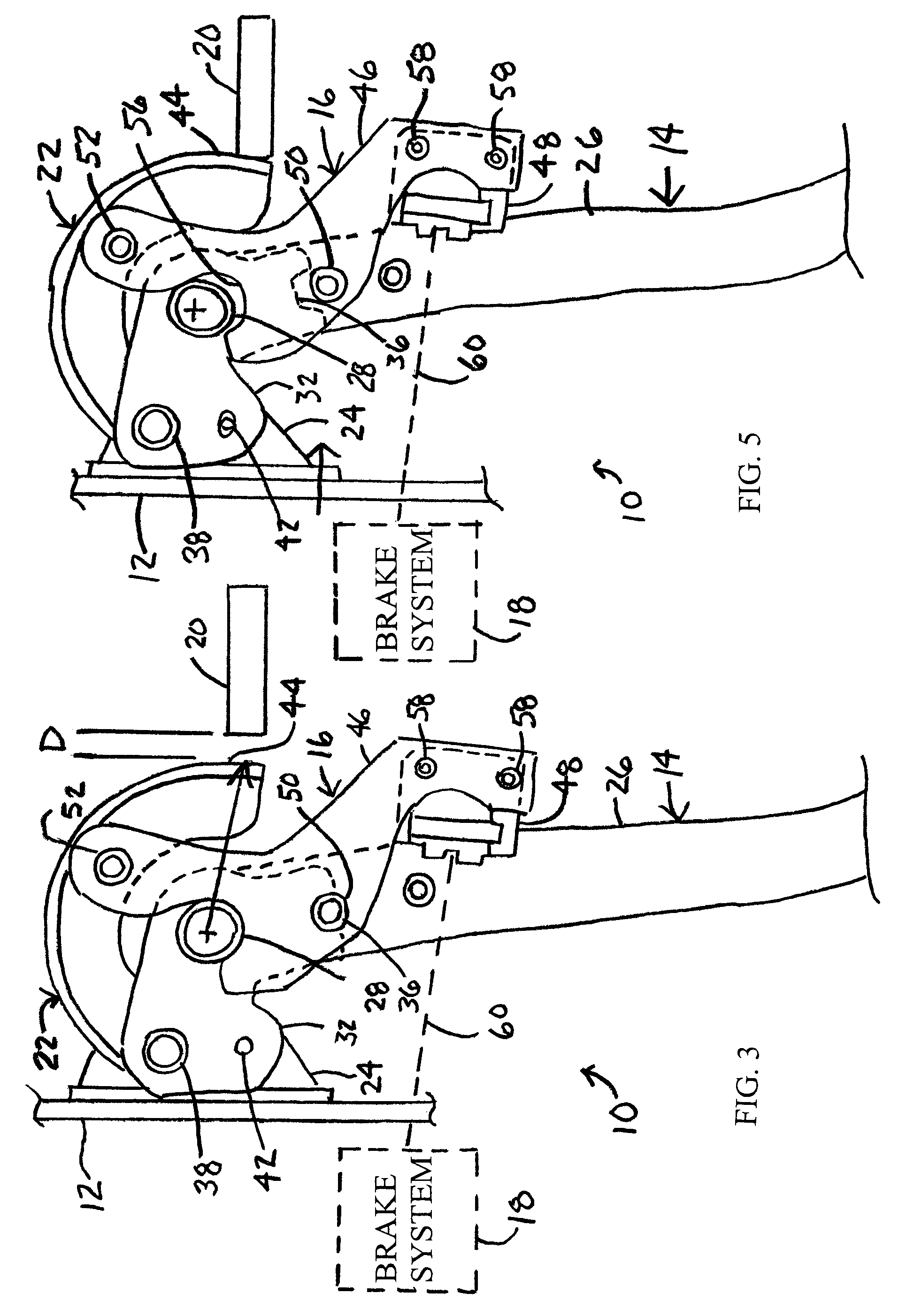
[0026]It will be apparent to those skilled in the art, that is, to those who have knowledge or experience in this area of technology, that many uses and design variations are possible for the improved control pedal assemblies disclosed herein. The following detailed discussion of various alternative and preferred embodiments will illustrate the general principles of the invention with reference to a brake pedal assembly for use with a motor vehicle. Other embodiments suitable for other applications will be apparent to those skilled in the art given the benefit of this disclosure.

[0027]FIGS. 1 to 6 illustrate a vehicle 10 according to a first embodiment of the present invention. The illustrated vehicle 10 includes a first vehicle structure 12, a pedal or pedal assembly 14 pivotably connected to the first vehicle structure for pivoting movement in a normal operating range between a rearward rest or unapplied position and a forward fully-applied position, a control attachment 16 operab...


PUM


Abstract

A vehicle includes a first structure, a pedal pivotably connected to the first structure for pivoting between rest and fully-applied positions, a control attachment connecting the pedal to a vehicle system to be controlled, a second structure located rearward of the pedal, and an engagement bracket connected to the pedal to engage the second structure upon rearward movement of the pedal during a vehicle frontal collision. The control attachment is connected to the engagement bracket and disengages from the pedal so that the pedal pivots independent of the control system when the engagement bracket strikes the second structure with a predetermined force. There is a constant distance between the engagement bracket and the second structure as the pedal pivots so that the position of the pedal does not affect the disengagement of the control attachment during the frontal collision.

Description

CROSS-REFERENCE TO RELATED APPLICATIONS[0001]Not ApplicableSTATEMENT REGARDING FEDERALLY SPONSORED RESEARCH[0002]Not ApplicableREFERENCE TO MICROFICHE APPENDIX[0003]Not ApplicableFIELD OF THE INVENTION[0004]The field of the present invention generally relates to control pedal assemblies for motor vehicles and, more particularly, to such control pedal assemblies which decouple during frontal vehicle collisions.BACKGROUND OF THE INVENTION[0005]Control pedals are typically provided in a motor vehicle, such as an automobile, which are foot operated by the driver. Separate control pedals are typically provided for operating vehicle brakes and an engine throttle. When the motor vehicle has a manual transmission, a third control pedal is provided for operating a transmission clutch. Each control pedal typically has a pedal arm mounted to pivot between an at-rest or unapplied position and a fully applied position. Control pedals of this type typically include a mechanism that connects the p...

Claims


Application Information

Patent Timeline
Patent Type & Authority Patents(United States)
IPC IPC(8): B60R21/08
CPCB60K23/02B60K26/02B60R21/09B60T7/065G05G1/323
Inventor ALLEN, JAMES ROBERTECKERLE, BRIAN JOHNBOOHER, JASON ALLEN
Owner DURA GLOBAL TECH
Learn More