
Image copier and image copying method

a copier and image technology, applied in the field of image copier and image copying method, can solve problems such as cost increas

Inactive Publication Date: 2010-08-17
KK TOSHIBA +1
View PDF25 Cites 13 Cited by
  • Summary
  • Abstract
  • Description
  • Claims
  • Application Information

AI Technical Summary

Benefits of technology

The invention aims to provide an image copier and method that can prevent the bottom side of a document from being copied while still detecting the size of the document. To achieve this, the copier includes a scanner that uses a light-emitting element to detect the size of the original document, a controller to adjust the light-emitting element based on the thickness of the document, and a specific region determination unit to identify a specific region of the document. Additionally, a background correction unit is used to adjust the output value from the photoelectric element based on a preset arithmetic expression. This results in a more accurate and efficient image processing process.

Problems solved by technology

However, in an image processing device utilizing the technique disclosed in Japanese Patent Laid-Open “JP-A-60-8835”, a cost increase can result from the need for the shielding plate for shielding the sensor hole and a driver for sliding the shield plate.

Method used


Image

  • Image copier and image copying method
  • Image copier and image copying method
  • Image copier and image copying method

Examples


first embodiment

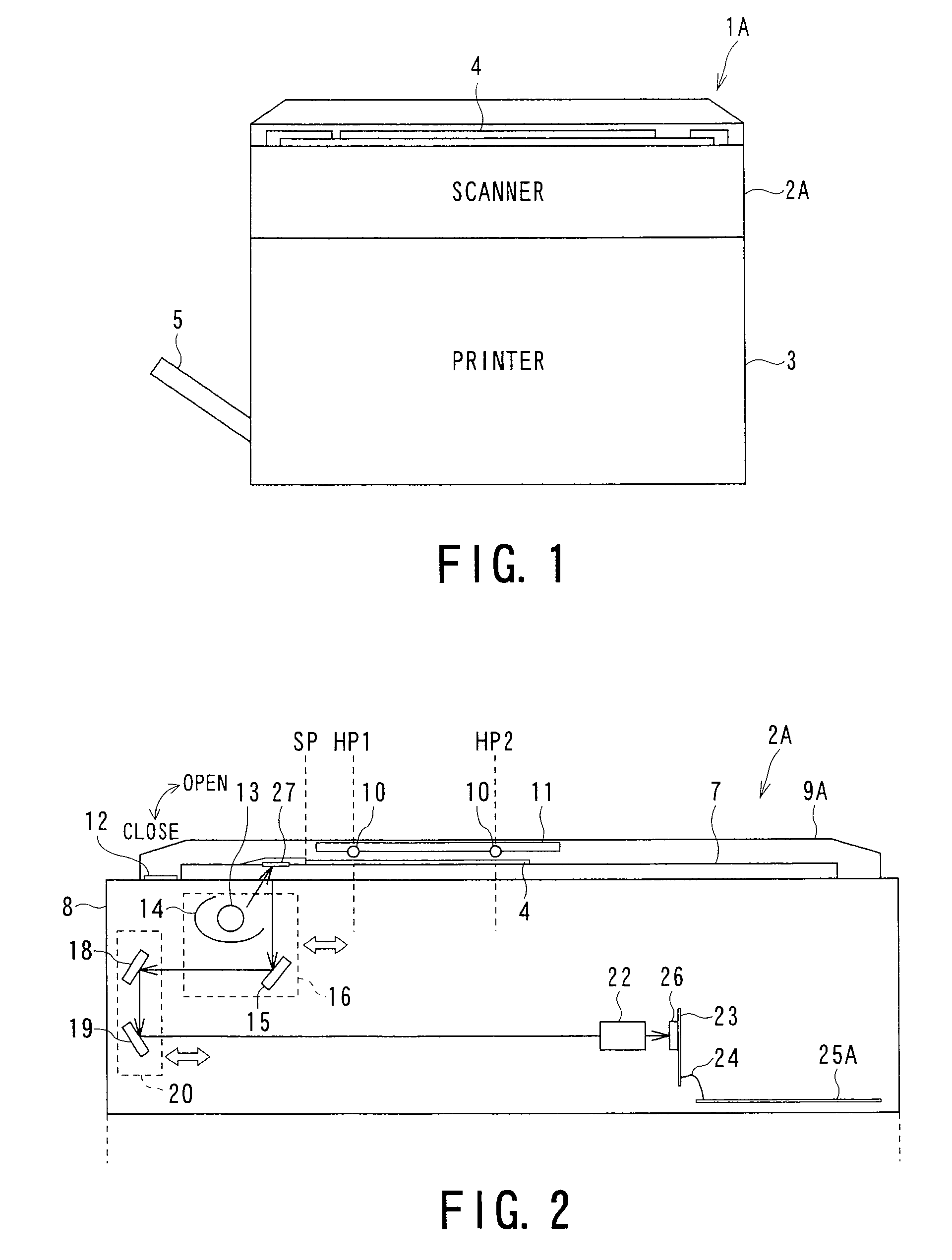
[0040]FIG. 1 is a schematic illustration of a configuration of an image copier 1A which is an example of an image copier according to a first embodiment of the invention.

[0041]The image copier 1A includes a scanner 2A for reading an image, and a printer 3 for forming the image and printing the formed image on a sheet.

[0042]The scanner 2A reads an original document 4 positioned to read the image. In the case where the read image is formed, the scanner 2A transmits the information of the read image to the printer 3.

[0043]The printer 3 forms the image on a sheet based on the information of the image to be formed, and then prints out the sheet on which the image has been formed to a sheet discharge tray 5.

[0044]Incidentally, although the image copier 1A further includes a system controller to perform a control and a control panel as a user interface, they are omitted in FIG. 1 (see FIG. 9 to FIG. 11).

[0045]Further, there is also a case where the scanner 2A does not transmit the read ima...

second embodiment

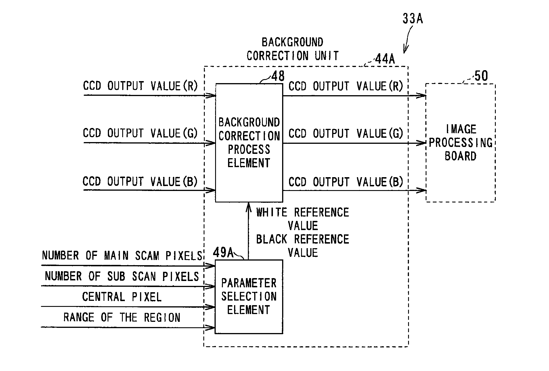
[0158]An image copier according to a second embodiment of the invention has a configuration obtained by replacing the image processing circuit 33A of the scanner 2A in the image copier 1A with an image processing circuit 33B. The image processing circuit 33B is different from the image processing circuit 33A in that the image processing circuit 33B has a background correction unit 44B, whereas the image processing circuit 33A has the background correction unit 44A.

[0159]That is, the image copier according to the second embodiment of the invention is different from the image copier 1A in that it includes the image processing circuit 33B having the background correction unit 44B instead of the image processing circuit 33A having the background correction unit 44A, although there is no substantial difference between them in other aspects.

[0160]Therefore, in the description of the image copier according to the second embodiment of the invention, elements which are not substantially diff...

third embodiment

[0184]An image copier according to a third embodiment of the invention is a version of the image copier according to the first embodiment added with the function of detecting the thickness of an original document (hereinafter referred to as an original document thickness detecting function).

[0185]FIG. 18 is an illustration for explaining a configuration and objects of control of a control board 25C of an image copier 1C which is an example of an image copier according to the third embodiment of the invention.

[0186]As shown in FIG. 18, the image copier 1C is a version of the image copier 1A in which the image processing circuit 33A is replaced with an image processing circuit 33C having an original document thickness detection unit 81 having the original document thickness detecting function. The image processing circuit 33C also includes a background correction unit 44C which replaces the background correction unit 44A provided in the image processing circuit 33A.

[0187]That is, elem...


PUM


Abstract

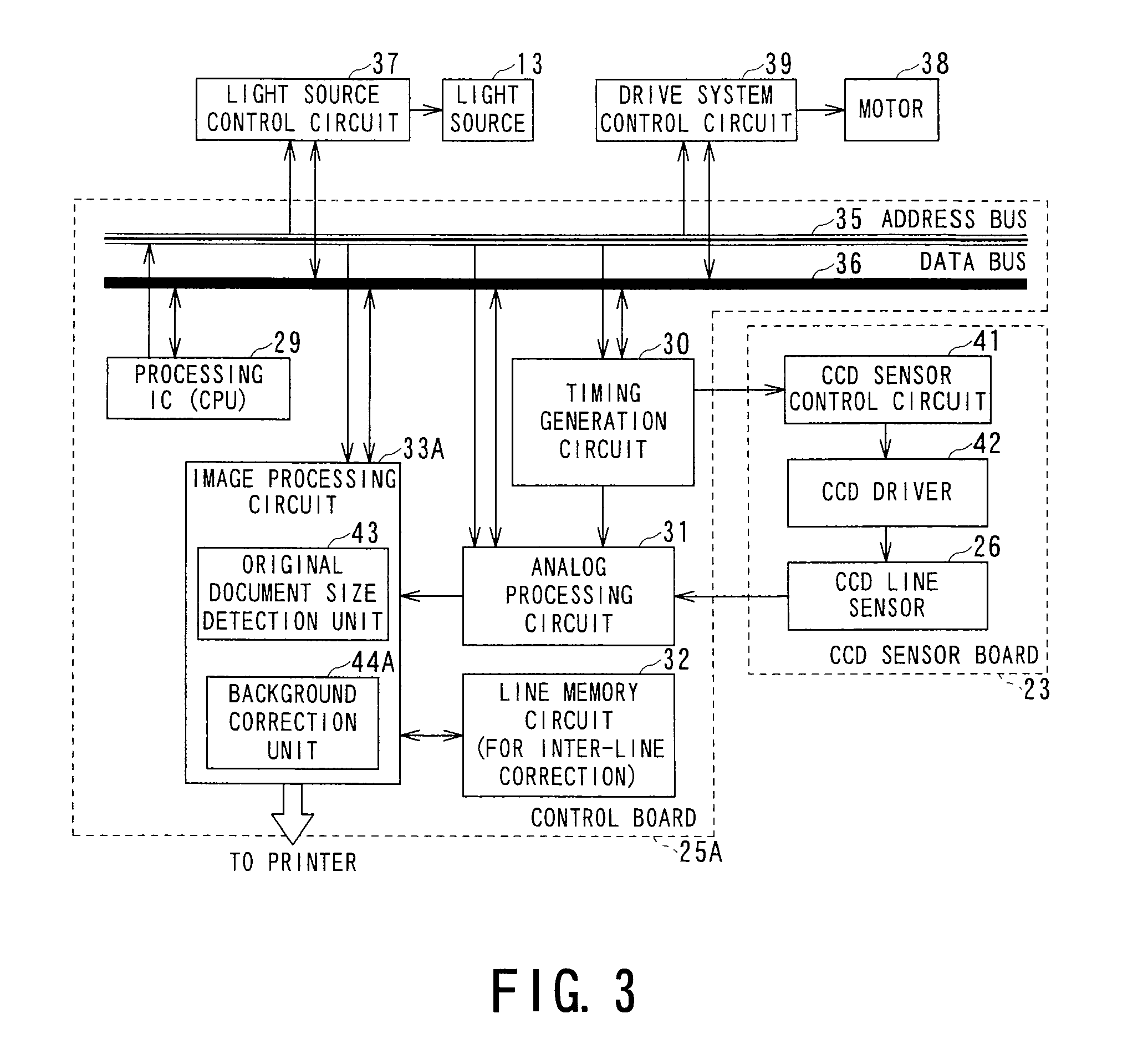
An image copier according to the invention comprises a scanner for reading an image and a printer for forming an image on sheet, and the scanner includes a document table for positioning an original document from which an image is to be read; a document holding cover holding the original document on the original document table and having a light-emitting element for detecting the size of an original document which emits light when the size of the original document is detected, a light source for irradiating the original document with light when an image on the original document is read, a light-receiving element for image reading which receives reflected light from the original document, a controller for the light-emitting element for detecting the size of an original document which controls the light-emitting element for detecting the thickness of the original document, a specific region determination unit for identifying a specific region based on the numbers of pixels in a main scanning direction and a sub scanning direction of image data, and a background correction unit for performing a process of correcting the background of an image which has been read. In the image copier according to the invention, see-through copying of the bottom side can be suppressed by performing a background correction process after an image is read without blocking a sensor hole of a sensor for detecting the size of the original document from light.

Description

BACKGROUND OF THE INVENTION[0001]1. Field of the Invention[0002]The present invention relates to an image copier and an image copying method and, particularly, to an image copier and image copying method in which an image on an original document is read while suppressing the see-through copying of the bottom side without shielding a sensor hole of a sensor for detecting the document size from light.[0003]2. Related Art[0004]Japanese Patent Laid-Open “JP-A-60-8835” discloses a copier platen cover including a sensor for detecting the size of an original document provided in the platen cover.[0005]In the copier platen cover disclosed in Japanese Patent Laid-Open “JP-A-60-8835”, a sensor hole is provided on a surface thereof adjacent to a platen glass, and a shield plate is disposed inside the surface adjacent to the platen glass. The shield plate of the copier platen cover is slid during copying to shield the sensor hole.[0006]However, in an image processing device utilizing the techni...

Claims


Application Information

Patent Timeline
Patent Type & Authority Patents(United States)
IPC IPC(8): H04N1/38H04N1/04
CPCH04N1/4095
Inventor SHODA, HIROKAZUIDE, NAOAKIHASHIZUME, YUSUKE
Owner KK TOSHIBA
Learn More