Door handle device

a technology for door handles and handle parts, applied in the direction of mechanical control devices, keyhole guards, instruments, etc., can solve the problems of small rattling in the gap between these two members, abnormal noise, and insufficient provision of key cylinder parts, so as to inhibit the rattling of the handle parts and reduce the occurrence of abnormal noises

Active Publication Date: 2010-08-24
AISIN SEIKI KK
View PDF40 Cites 10 Cited by
  • Summary
  • Abstract
  • Description
  • Claims
  • Application Information

AI Technical Summary

Benefits of technology

[0008]The present invention has been made in view of the conventional circumstances described above. It is an object of the present invention to provide a door handle device that is capable of inhibiting the rattling of a handle member and that is capable of reducing the occurrence of abnormal noises between a handle member that is mounted on a handle frame member, and a key cylinder member.
[0010]Therefore, according to the door handle device in an aspect of the present invention, rattling of the handle member is inhibited, and since the handle member is mounted on the handle frame member, the occurrence of abnormal noises between the handle member and the key lock member is reduced.

Problems solved by technology

However, in the door handle device described above, a key cylinder member is not provided integrally.
However, the handle member is swingably mounted on the handle frame member, and thus, a slight degree of rattling may occur in the gap between these two members.
Therefore, if the gap between the handle member and the key cylinder member is minimized, the handle member and the key cylinder member can collide with each other and produce abnormal noise.

Method used


Image

  • Door handle device
  • Door handle device
  • Door handle device

Examples


Embodiment Construction

[0020]An embodiment of a door handle device of the present invention will now be described with reference to the accompanying drawings.

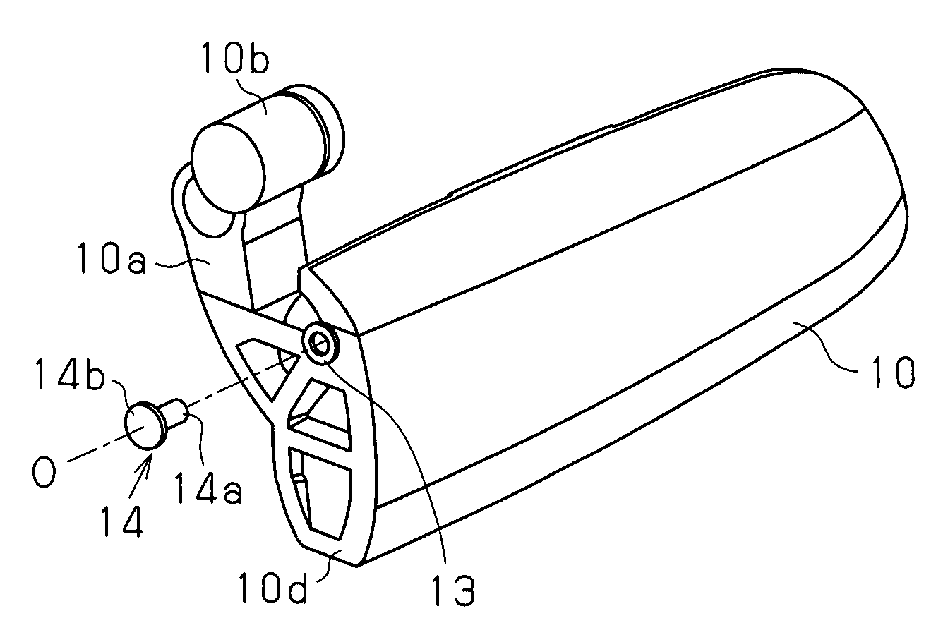
[0021]The door handle device according to the present embodiment is provided with the parts listed below. First, as illustrated in FIG. 1, a handle member 10 (for example, a metallic or a plated synthetic resin handle member) is prepared as a pull-up type of outside door handle. The handle member 10 is provided with an arm portion 10a that extends in an upward direction from a rear surface. A counterweight 10b is mounted on an upper end of the arm portion 10a.

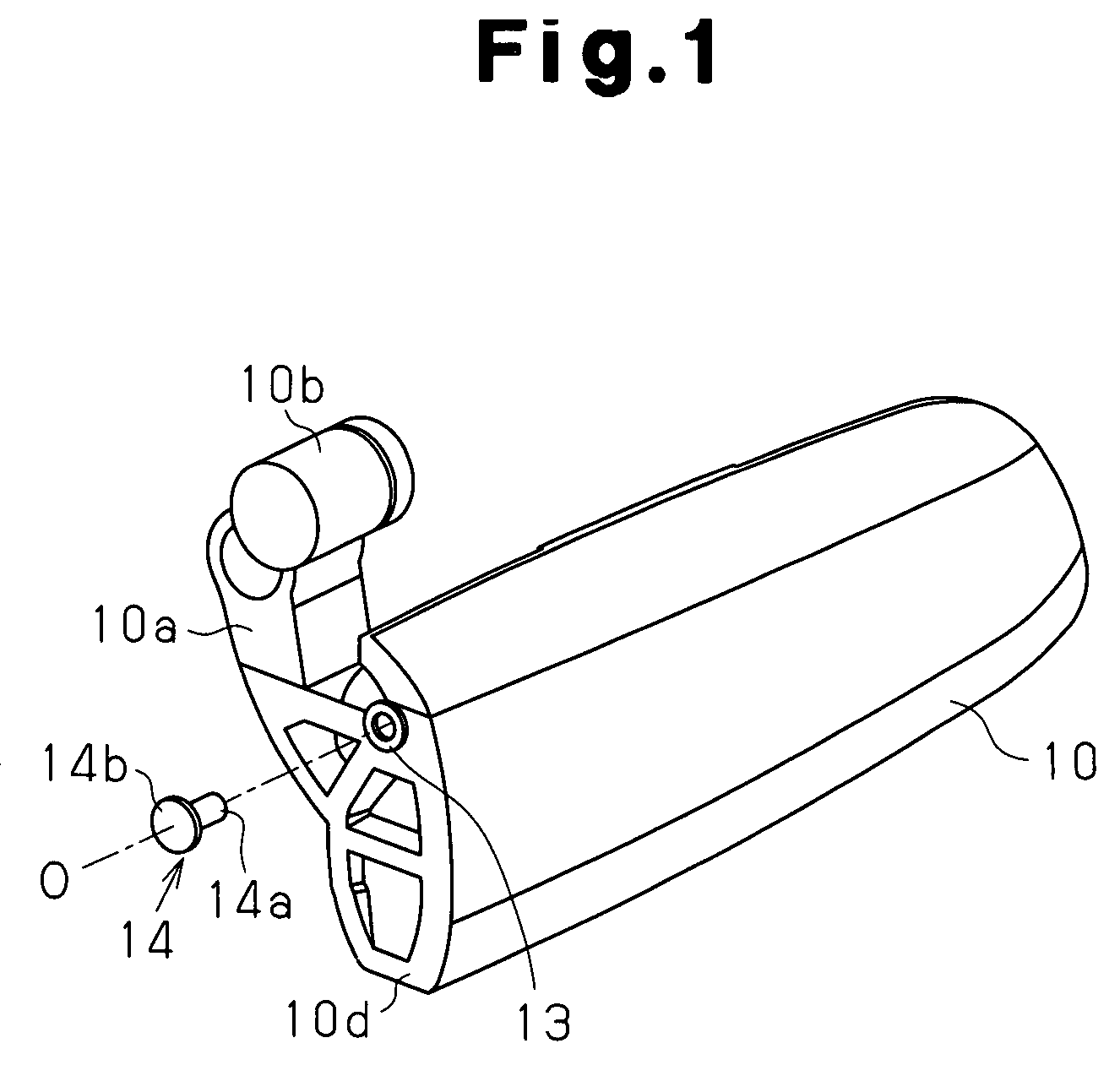
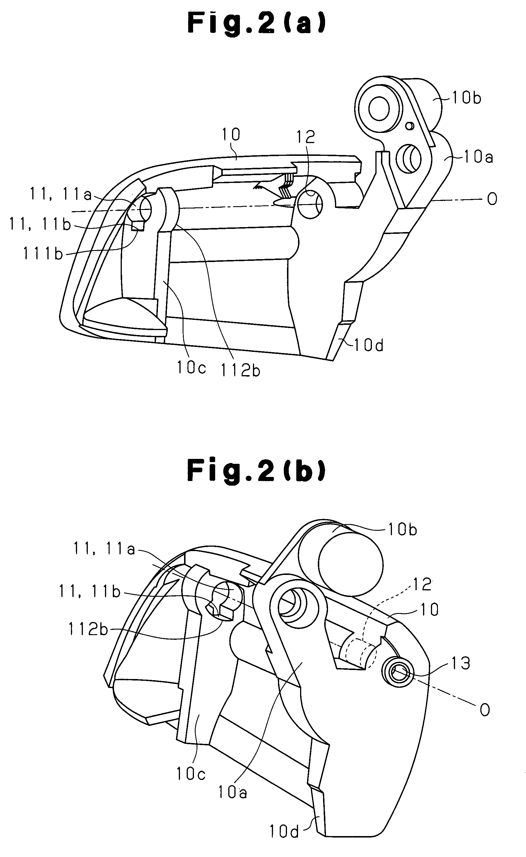
[0022]As illustrated in FIG. 2(a) and FIG. 2(b), on the rear surface of the handle member 10, a first wall portion 10c is provided in a protruding manner at a position spaced laterally from the arm portion 10a. A first engagement hole 11 extending horizontally is penetrated and formed at an upper part of the first wall portion 10c. The first engagement hole 11 is composed of a circular portion ...


PUM


Abstract

A door handle device is provided with: a handle member 10; a handle frame member 20 swingably supporting the handle member 10, the handle frame member being fixed to a door 50; and a key cylinder cover 49 integrated with a key cylinder device 30 capable of locking the door 50. The handle member 10 has a swing center axis O about which the handle member 10 swings relative to the handle frame member 20. On the slide center axis O, an engagement pin 14 is interposed between the handle member 10 and the key cylinder cover 49.

Description

BACKGROUND OF THE INVENTION[0001]1. Field of the Invention[0002]The present invention relates to a door handle device, and in particular, to a door handle device which is suitable as an outside door handle.[0003]2. Background of the Invention[0004]A conventional handle device has been known that is disclosed in patent document 1. The door handle device is provided with a handle member and a base. The base is fixed to a door in a state in which the handle member can be swingably supported. A cushion rubber is mounted on the base. By means of the cushion rubber, a closed position of the handle member can be restricted, and in this manner, a sophisticated operational sound can be achieved at a time that a handle is returned to its original position.[0005]However, in the door handle device described above, a key cylinder member is not provided integrally. A key cylinder member is provided on the door in addition to the door handle device.[0006]In this respect, in recent years, a door ha...

Claims


Application Information

Patent Timeline
Patent Type & Authority Patents(United States)
IPC IPC(8): B60R25/02
CPCE05B85/18E05B79/06E05B85/06E05B77/42E05B77/36E05B77/06Y10T292/57Y10T70/5761Y10T292/688Y10T70/5832Y10T70/577
Inventor TANIMOTO, TETSUROUNISHIKAWA, MASAKISUZUKI, YOSHIMASA
Owner AISIN SEIKI KK
Why Eureka
Try Eureka