Image stabilizing apparatus

a technology lens shift, which is applied in the direction of projectors, instruments, printing, etc., can solve the problems of increasing the relative material cost of magnets and difficult stabilizing the positioning of camera bodies, and achieve the effects of reducing the size and weight of image stabilizing apparatus, and reducing the size and weight of actuators

Inactive Publication Date: 2010-08-24
PANASONIC CORP
View PDF5 Cites 0 Cited by
  • Summary
  • Abstract
  • Description
  • Claims
  • Application Information

AI Technical Summary

Benefits of technology

[0016]An object of the present invention is to provide an image stabilizing apparatus capable of realizing size, weight and cost reduction. A further object of the present invention is to provide a lens barrel and an image sensing apparatus that include such an image stabilizing apparatus.
[0018]According to this configuration, sufficient thrust can be obtained even if a small magnet is used, since the gap between the position detection sensor and the opposing yoke can be secured even if the gap between the flat coil and the magnet is narrowed.
[0019]With the image stabilizing apparatus of the present invention, reducing the size and weight of an actuator is possible while securing sufficient thrust, thereby enabling reduction in the size and weight of an image stabilizing apparatus to be realized.

Problems solved by technology

However, with digital still cameras, stabilizing the positioning of the camera body is difficult because their smallness and lightness means that the camera shakes readily when holding the camera to take a shot.
Also, because a portion of the magnet 120 is shaved off, more magnetic material is required to form magnets of the same volume, increasing the relative material cost of the magnets.

Method used


Image

  • Image stabilizing apparatus
  • Image stabilizing apparatus
  • Image stabilizing apparatus

Examples


embodiment 1

[1. Configuration and Operation of Image Sensing Apparatus]

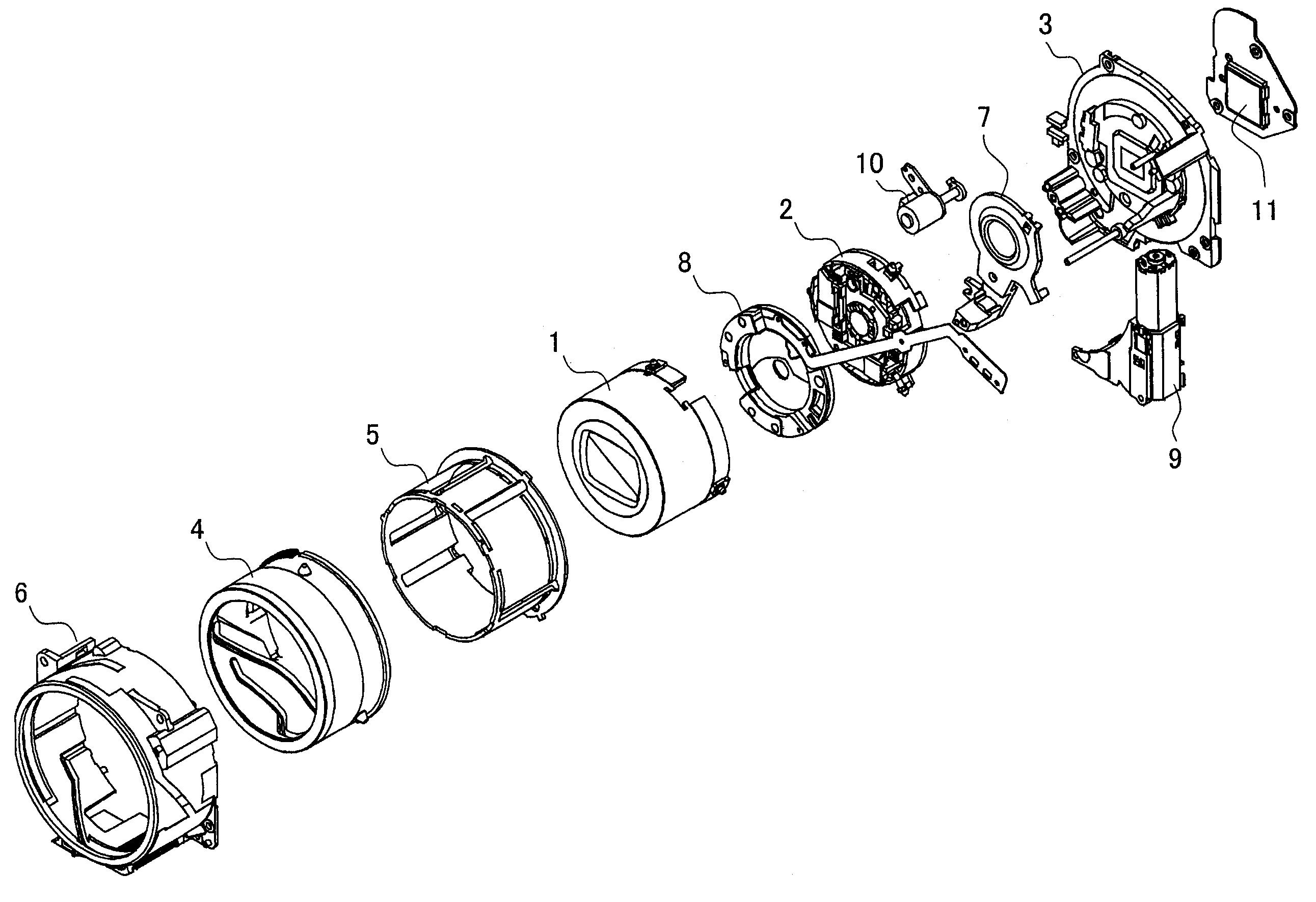
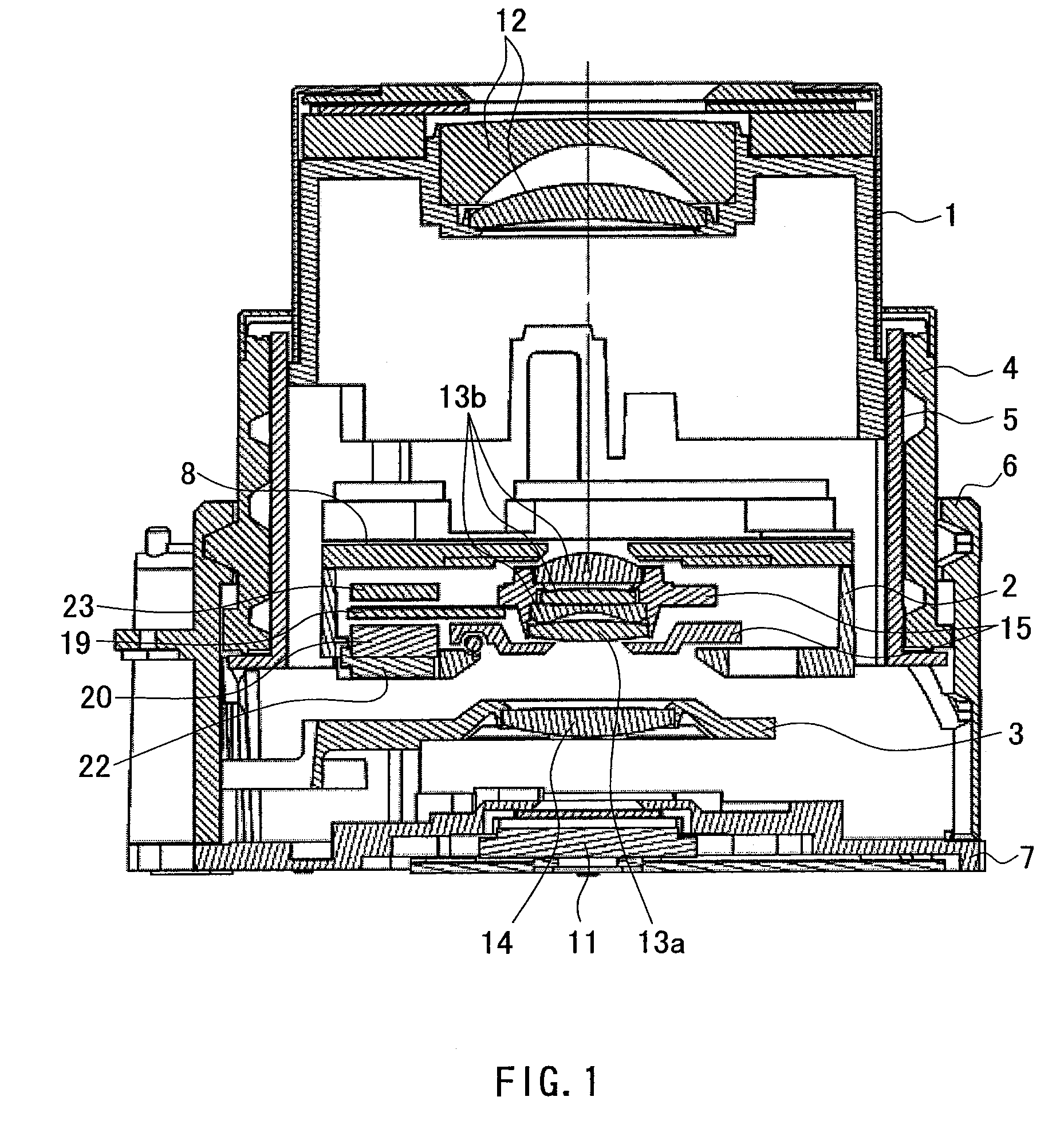
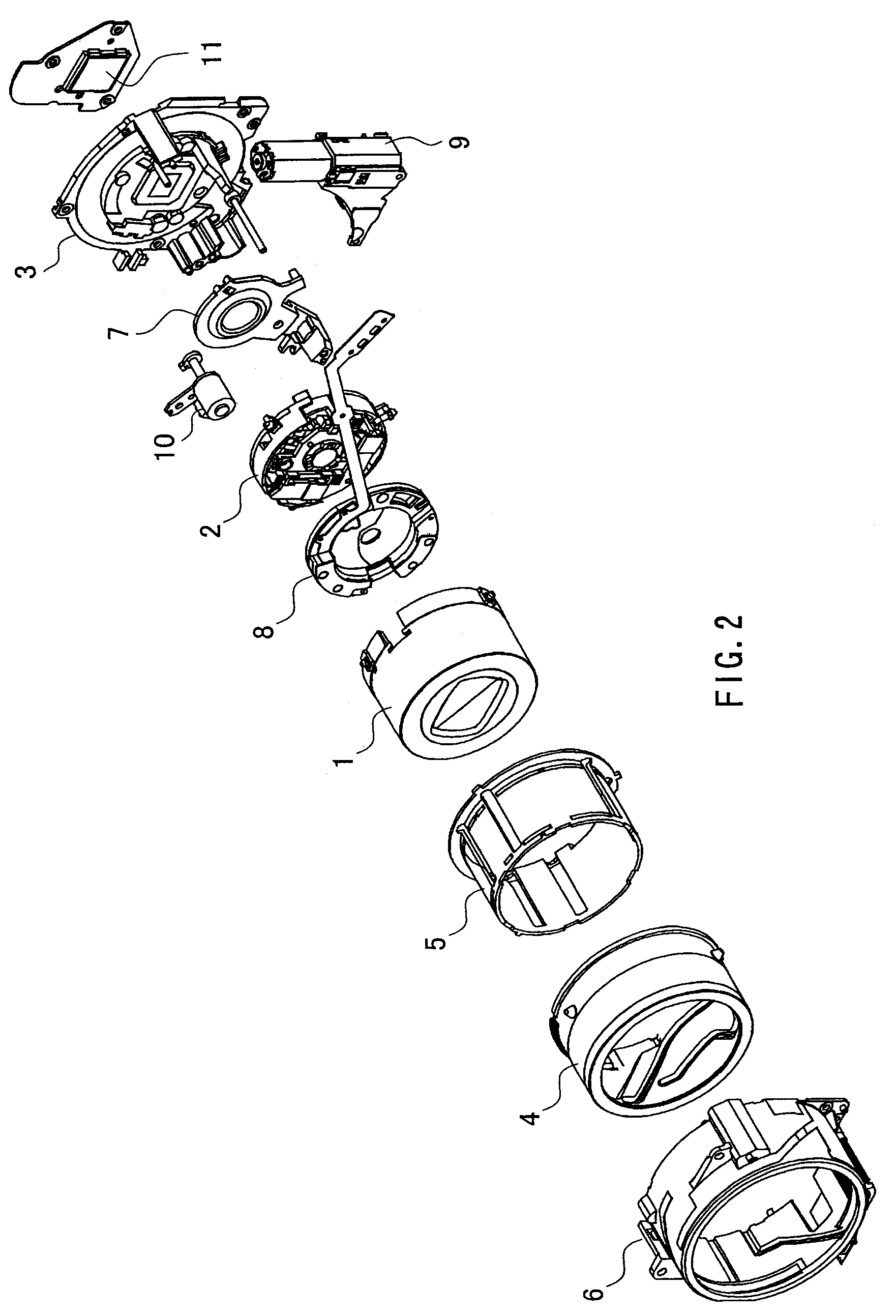
[0032]FIG. 1 is a cross-sectional view of a lens barrel according to embodiment 1. FIG. 2 is an exploded perspective view of the lens barrel.

[0033]As shown in FIGS. 1 and 2, the lens barrel of embodiment 1 includes a first moving frame 1, a second moving frame 2, a third moving frame 3, a drive frame 4, a through frame 5, a fixed frame 6, and a base unit 7.

[0034]The first moving frame 1 holds a first lens group 12 that includes an objective lens. The first moving frame 1 is held movably in the optical axis direction by the drive frame 4.

[0035]The second moving frame 2 (holding frame) includes a shutter unit 8, a pitching frame 15, a laminated substrate 19, a magnet 20, a hall element 21 (see FIG. 3), a back yoke 22, an opposing yoke 23 and a flexible printed circuit board 24. The second moving frame 2 is supported by the drive frame 4 so as to be movable in the optical axis direction. The second moving frame 2 holds a second...

embodiment 2

[0079]In embodiment 2, a configuration is shown that improves on the opposing yoke of embodiment 1.

[0080]FIG. 7A is a perspective view showing an opposing yoke according to embodiment 2. FIG. 7B is a cross-sectional view of a C-C portion of FIG. 7A. Note that the configuration of the image stabilizing apparatus of embodiment 2 is the same as embodiment 1 except for the opposing yoke 31.

[0081]The opposing yoke 23 shown in embodiment 1 is stepped (indentation-type recesses 23a, 23b) up to and including an outer periphery thereof, as shown in FIG. 5. That is, the indentation-type recesses 23a and 23b are formed in the surface of the opposing yoke 23 that opposes the hall element 21 up to the edge of the opposing yoke 23 on the short side.

[0082]The opposing yoke 31 shown in embodiment 2 is only stepped (recesses 31a, 31b) in a portion of the opposing yoke 31 that opposes the hall element 21, as shown in FIG. 7B. That is, flat portions 31c and 31d that are flush with the main surface of ...


PUM


Abstract

An image stabilizing apparatus of the present invention includes a laminated substrate 19 that has a coil pattern, a hall element 21 fixed to the laminated substrate 19, a magnet 20, a back yoke 22, an opposing yoke 23, and a flexible printed circuit board for wiring the coil pattern on the laminated substrate and the hall element 21, the opposing yoke 23 being stepped (indentation-type recesses 23a, 23b) in a portion opposing the hall element 21. Reduction in size, weight and cost are thereby realized in a lens-shift image stabilizing apparatus.

Description

BACKGROUND OF THE INVENTION[0001]1. Field of the Invention[0002]The present invention relates to a so-called lens-shift image stabilizing apparatus that performs image stabilization by moving some of the lenses in an optical axis direction and a vertical direction. The present invention also relates to a lens barrel that includes such an image stabilizing apparatus, and an image sensing apparatus that includes the image stabilizing apparatus or the lens barrel, and more particularly to an image sensing apparatus such as a video camera or a digital still camera.[0003]2. Description of the Related Art[0004]In recent years, digital still cameras have seen a dramatic improvement in usability, in addition to reductions in size and weight and better image quality. As a result, digital still cameras have become widespread, replacing conventional silver halide cameras. Compared with silver halide cameras, which capture images by exposing an optical image on film, digital still cameras are a...

Claims


Application Information

Patent Timeline
Patent Type & Authority Patents(United States)
IPC IPC(8): G02B27/64G03B5/00G03B30/00
CPCG02B27/646
Inventor FUJINAKA, HIROYASUKOIKE, TAKASHIKUWAHARA, TAKUMIHASEGAWA, ATSUSHI
Owner PANASONIC CORP
Why Eureka
Try Eureka