Image forming apparatus

a technology of forming apparatus and forming tube, which is applied in the direction of electrographic process apparatus, instruments, optics, etc., can solve the problems of difficult suppression of the effect of space s, difficult to difficult to completely eliminate the defect of glossiness, etc., and achieve excellent toner image glossiness

Inactive Publication Date: 2010-08-24
CANON KK
View PDF23 Cites 35 Cited by
  • Summary
  • Abstract
  • Description
  • Claims
  • Application Information

AI Technical Summary

Benefits of technology

[0012]Therefore, the present invention has been made in view of the above-mentioned technical problems. An object of the present invention is to provide an image forming apparatus capable of obtaining a high-quality toner image excellent in glossiness.
[0014]According to the present invention, it is possible to obtain a high-quality toner image excellent in glossiness.

Problems solved by technology

Such the image forming method has a problem with how to obtain a surface of the recording material having toner formed thereon with smoothness and without a boundary between the toner and the surface of the recording material.
As described above, even when the glossy dedicated paper having the resin layer provided thereon and the belt fixing device are used, it is difficult to completely eliminate the defect in glossiness due to the bump α of the toner.
In particular, it is difficult to eliminate the defect in glossiness due to a dimple S1 (shown in FIG. 4D) which is generated by an effect of the bump of the toner image obtained before the toner image is fixed by the belt fixing device.
However, it is difficult to suppress the effect of the space S.

Method used


Image

  • Image forming apparatus
  • Image forming apparatus
  • Image forming apparatus

Examples


first embodiment

Mode

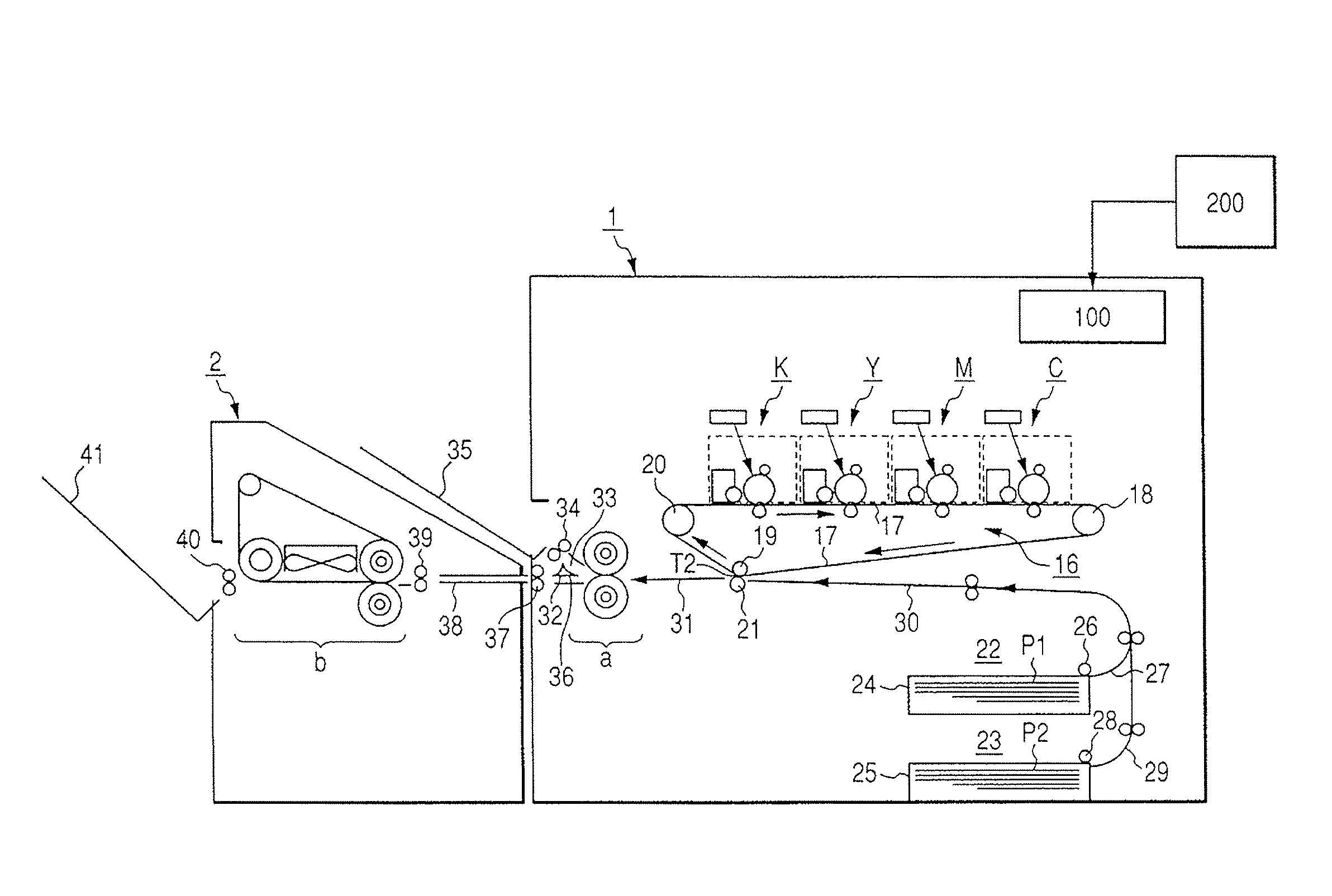
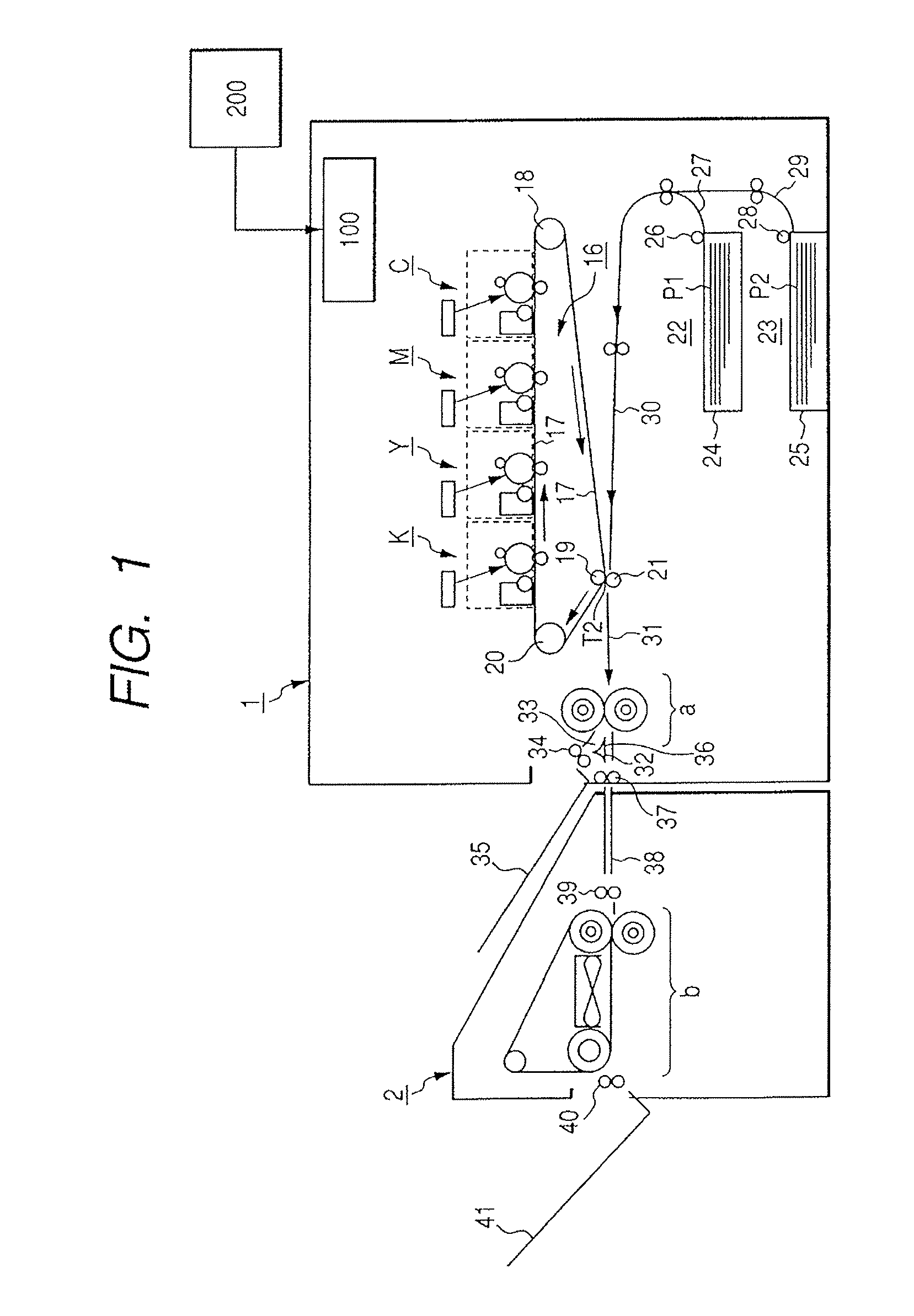
[0024](1) Overall General Description as to an Example of an Image Forming Apparatus

[0025]FIG. 1 is a schematic structural view of an image forming apparatus according a first embodiment mode of the present invention. The image forming apparatus includes an image forming apparatus main body (hereinafter, referred to as “apparatus main body”) 1 and a belt fixing device unit (i.e., glossiness applying device) 2. The belt fixing device unit 2 is connected on an outlet side of the apparatus main body 1. In this embodiment, the belt fixing device unit 2 is an optional apparatus as a housing separated from the apparatus main body 1, and is capable of outputting an image onto glossy dedicated paper such as a photograph and various types of sheets.

[0026]The apparatus main body 1 is an electrophotographic four-color full-color image forming apparatus (i.e., tandem color recording apparatus). An external host apparatus 200 such as a color image reading apparatus or a personal computer is ...

embodiment 1

[0099]In this embodiment, the pressing force applied between the fixing roller 51 and the pressure roller 52 of the first fixing device a was released, and the fixing roller 51 and the pressure roller 52 were spaced apart from each other. Then, the recording material P2 bearing the toner image was allowed to pass between the fixing roller 51 and the pressure roller 52 spaced apart from each other. Both the rollers 51 and 52 were rotationally driven at a surface speed (i.e., fixing speed) of 55 mm / s. The respective surface temperatures of the fixing roller 51 and the pressure roller 52 were controlled to be maintained at 175° C. By those settings, the pressing force is not applied to the toner image formed on the recording material P, and only the radiation of heat of the rollers is applied to the toner image. Thus, only the radiation of heat of the rollers is applied to the unfixed toner image, thereby making it possible to suppress dispersion of toner within the apparatus.

embodiment 2

[0100]In this embodiment, the pressing force applied between the fixing roller 51 and the pressure roller 52 of the first fixing device a was set to 300 N, and the respective surface temperatures of both the rollers were controlled to be maintained at 50° C. Both the rollers 51 and 52 were rotationally driven at the surface speed (i.e., fixing speed) of 55 mm / s. The first fixing device a controls a cooling fan (not shown) and heating by a heater included in the rollers to regulate the surface temperatures of both the rollers to be maintained at 50° C.


PUM


Abstract

An image forming apparatus has a first recording mode of outputting the recording material without passing thru the glossiness applying device after fixing and a second recording mode using the glossiness applying device, and then outputting the recording material. In the latter recording mode (B), when a void ratio G of toner in the toner image not yet subjected to the glossing process by the glossiness applying device is defined by a thickness t1 of a toner layer on the recording material after fixing and before entering the glossiness applying device, and a thickness t2 of a toner layer on the recording material after passing through the glossiness applying device, satisfies the formula: G=100×(t1-t2) / t1. In the recording mode (B), fixing conditions for the fixing device and the glossiness applying device are respectively set so that the void ratio of toner satisfies a formula 15≦G≦60.

Description

[0001]This application is a continuation of International Application No. PCT / JP2006 / 316786, filed Aug. 21, 2006, which claims the benefit of Japanese Patent Application Nos. 2005-239771, filed Aug. 22, 2005 and 2006-216793, filed Aug. 9, 2006.BACKGROUND OF THE INVENTION[0002]1. Field of the Invention[0003]The present invention relates to an image forming apparatus capable of obtaining a toner image excellent in glossiness.[0004]2. Description of the Related Art[0005]Up to now, widely known is an image forming apparatus employing an electrophotographic process such as a copying machine, a printer, a facsimile machine, and a combined machine having functions thereof. In addition, a large number of image forming apparatuses for performing not only a monochromatic image formation but also a full-color image formation are commercially available.[0006]Further, with an increase in use of the image forming apparatuses employing the electrophotographic process in various fields, demands for...

Claims


Application Information

Patent Timeline
Patent Type & Authority Patents(United States)
IPC IPC(8): G03G15/00G03G15/20
CPCG03G15/6573G03G15/2021G03G2215/00805G03G2215/00755
Inventor CHIGONO, YASUNORIFUKATSU, MAKOTO
Owner CANON KK
Why Eureka
Try Eureka