Toolbox assembly

a toolbox and assembly technology, applied in the direction of rotating cabinets, mechanical controls, manufacturing tools, etc., can solve the problems of many of these toolbox assemblies that are not very sturdy, not aesthetically pleasing, and many of these toolbox assemblies are even broken, and are difficult to lock or unlock

Active Publication Date: 2010-08-31
GRELA LARRY MITCHELL
View PDF41 Cites 35 Cited by
  • Summary
  • Abstract
  • Description
  • Claims
  • Application Information

AI Technical Summary

Benefits of technology

[0012]It is a second non-limiting object of the present invention to provide a toolbox assembly which is sturdy, aesthetically pleasing, allows a wide range of storage strategies and items to be utilized and has enhanced functionality.
[0014]According to a second non-limiting aspect of the present invention, a selectively lockable toolbox assembly is provided and which includes at least a first and a second door and a latch assembly which allows the toolbox assembly to be selectively locked when the at least said first door is open and which further allows the at least first door to be selectively moved to a closed position after the toolbox assembly has been selectively locked.

Problems solved by technology

While these assemblies do allow such tools and other materials to be stored and selectively retrieved, they suffer from several drawbacks.
By way of example and without limitation, many of these toolbox assemblies are not aesthetically pleasing and are not very sturdy.
For example, many of these toolbox assemblies have unsightly weld type connections formed on several or all of the surfaces of the body and such connections undesirably disrupt the overall appearance of the assembly, and many of these toolbox assemblies bend or bow over time, due to the weight associated with the stored items and the fact that they are not structurally sturdy, and many of these toolbox assemblies even break.
Further, by way of example and without limitation, many of these toolbox assemblies are very difficult to lock or unlock, requiring a relatively large amount of strength to move the locking mechanism to the desired locked or unlocked position and these toolbox assemblies don't even allow the assembly to be locked unless all of the drawers are in a predetermined closed position.
Thus, one cannot lock the toolbox assembly with one of the drawers in an open and utilized position.
This is a particular significant drawback because oftentimes the user of the toolbox assembly, after performing much work with the stored tools, forgets to lock the assembly, thereby making the contained tools available for theft.
Unfortunately, this utility does not exist with current prior toolbox assemblies.
Further, these prior and current toolbox assemblies do not allow desired casters to be utilized (e.g., larger or more sturdy casters for particularly heavy toolbox assemblies and lighter casters for lighter toolbox assemblies), thereby increasing the probability of breakage (i.e., if lighter type casters were only used and the contained tools were particularly heavy and / or the toolbox assembly was utilized in a particularly harsh environment, such as that in which a large amount of vibration or movement occurred) and undesirably increasing the cost if relatively expensive casters were used in a situation in which they were not needed (i.e., where the toolbox assembly is not relatively heavy and the environment is not really harsh).
Further, these prior and current toolbox assemblies do not readily allow additional casters to be deployed if the need arises and in order to increase the sturdiness or ruggedness of the utilized toolbox assembly.
Yet further, these prior and current toolbox assemblies do not allow drawers to be readily interchangeable in order to accommodate different storage strategies or techniques of the various users of these toolbox assemblies and do not allow for differently shaped items to be readily stored within these assemblies.

Method used


Image

  • Toolbox assembly
  • Toolbox assembly
  • Toolbox assembly

Examples


Embodiment Construction

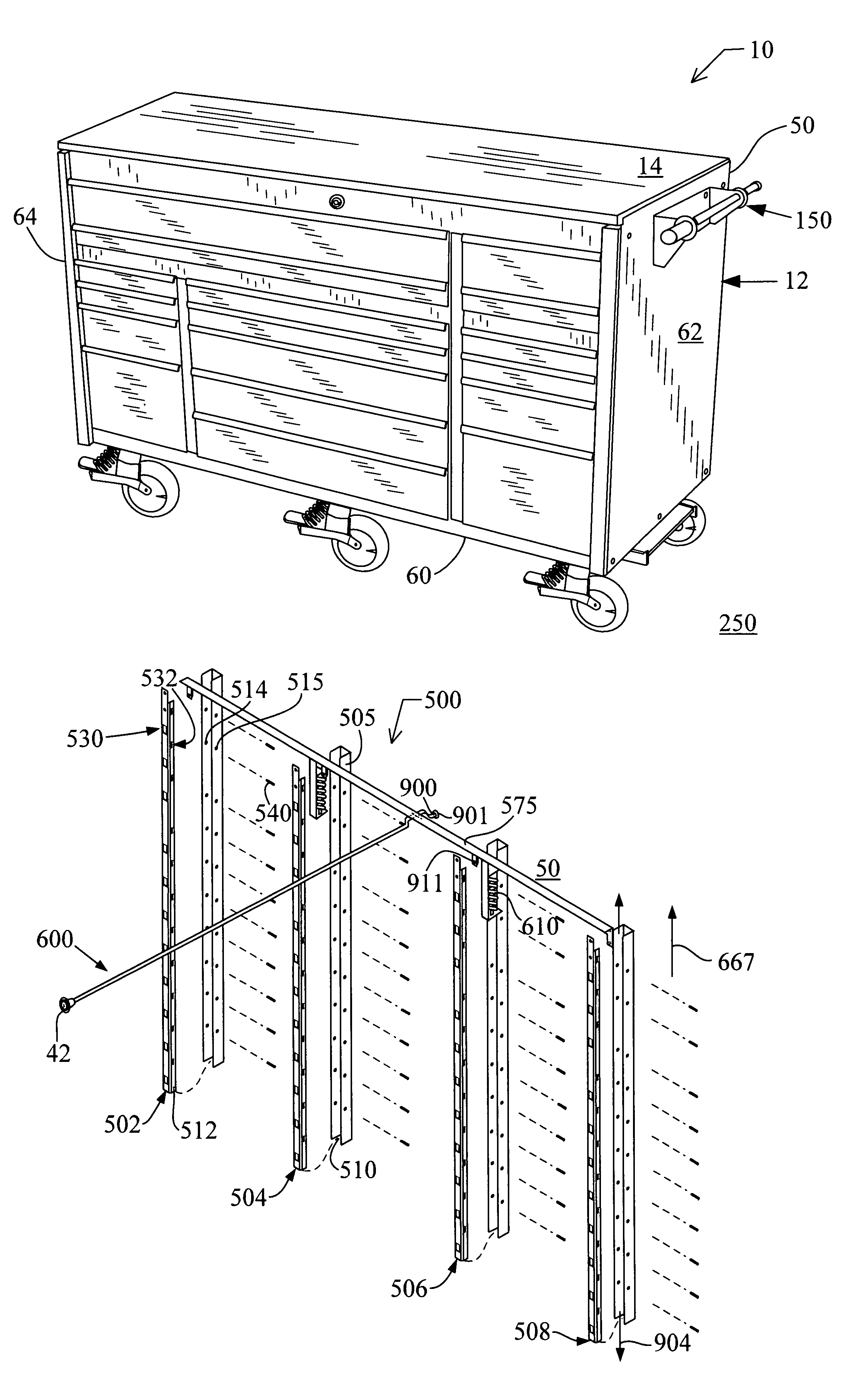
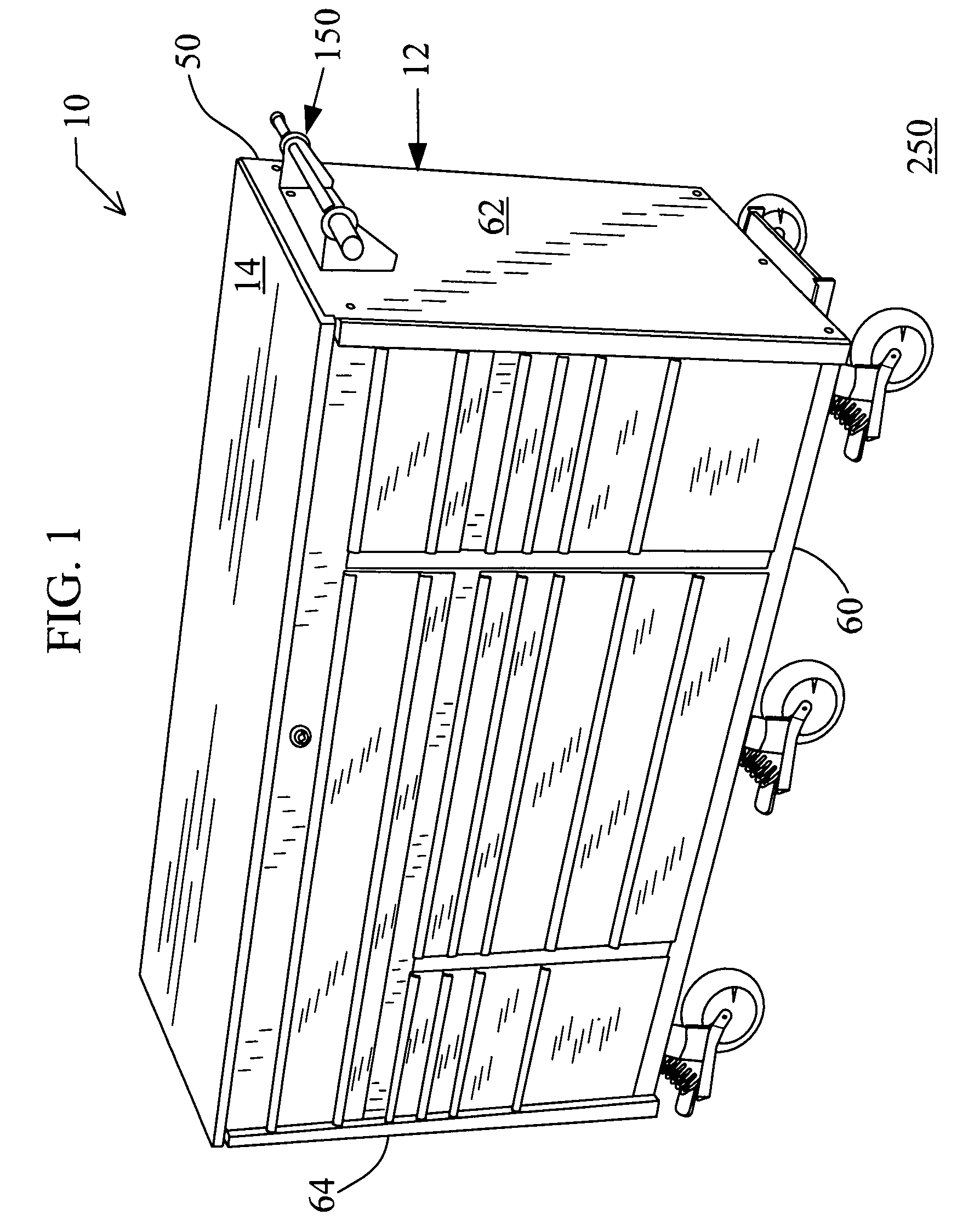
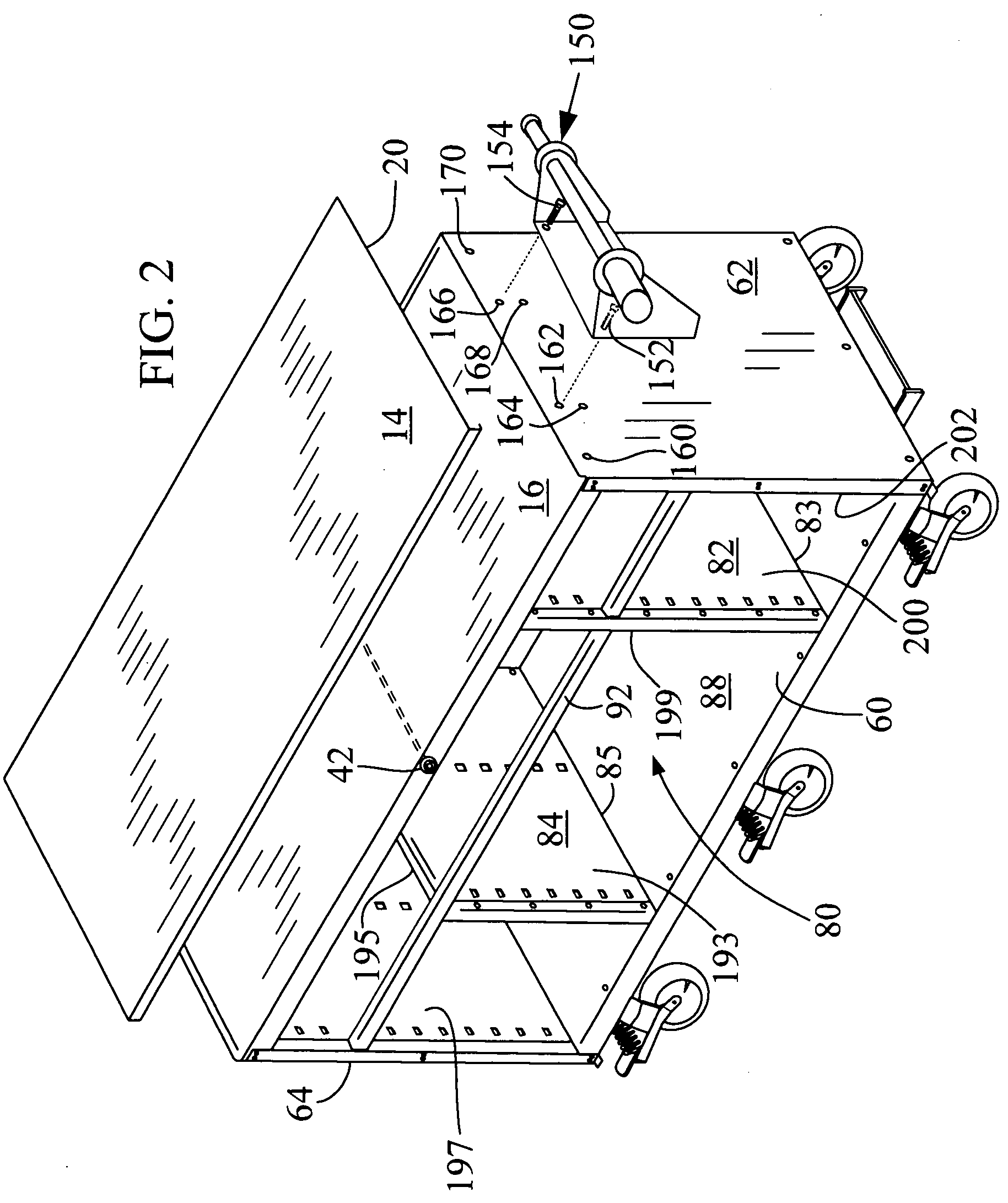
[0037]Referring now to FIGS. 1, 2, and 16, there is shown a toolbox assembly 10 which is made in accordance with the teachings of the preferred embodiment of the various inventions. Particularly, the toolbox assembly 10 includes a generally hollow body 12 which is selectively formed by a plurality of members which will be discussed below and which is adapted, as is evident from the discussion below, to selectively and movably receive drawers which are themselves adapted to selectively receive and store tools and / or other items and which allows these received tools and / or other items to be efficiently accessed and then later deposited into the toolbox assembly for secure storage. Thus, it should be appreciated that while we are referring to the assembly 10 as a “toolbox” assembly, many dissimilar items, other than tools, may be selectively deposited, stored, and retrieved from the assembly 10.

[0038]The toolbox assembly 12 includes a stainless steel top member 14 and a top member supp...


PUM


Abstract

A toolbox assembly 10 which is adapted to allow material to be easily and securely stored and retrieved and which is aesthetically pleasing and structurally sound.

Description

GENERAL BACKGROUND[0001]1. Field of the Invention[0002]The present invention generally relates to a toolbox assembly and more particularly to a toolbox assembly which is both aesthetically pleasing, which is sturdy, which is able to be easily locked, and which is highly functional and which allows items to be efficiently stored and accessed.[0003]2. Background of the Invention[0004]Toolbox assemblies are used to selectively store tools, such as automotive repair type tools, and other materials. While these assemblies do allow such tools and other materials to be stored and selectively retrieved, they suffer from several drawbacks.[0005]By way of example and without limitation, many of these toolbox assemblies are not aesthetically pleasing and are not very sturdy. For example, many of these toolbox assemblies have unsightly weld type connections formed on several or all of the surfaces of the body and such connections undesirably disrupt the overall appearance of the assembly, and m...

Claims


Application Information

Patent Timeline
Patent Type & Authority Patents(United States)
IPC IPC(8): E05B65/46E05B65/462
CPCB25H3/028B62B3/008E05B65/462Y10S312/902
Inventor GRELA, LARRY MITCHELLMANALANG, EDWIN DIZON
Owner GRELA LARRY MITCHELL
Why Eureka
Try Eureka