
Power management for electronic devices

a technology of power management and electronic devices, applied in power management, relays, high-level techniques, etc., can solve the problems of reduced convenience and reliability, increased power supply demand, and increased power consumption

Active Publication Date: 2010-08-31
HARMAN PROFESSIONAL INC
View PDF14 Cites 46 Cited by
  • Summary
  • Abstract
  • Description
  • Claims
  • Application Information

AI Technical Summary

Benefits of technology

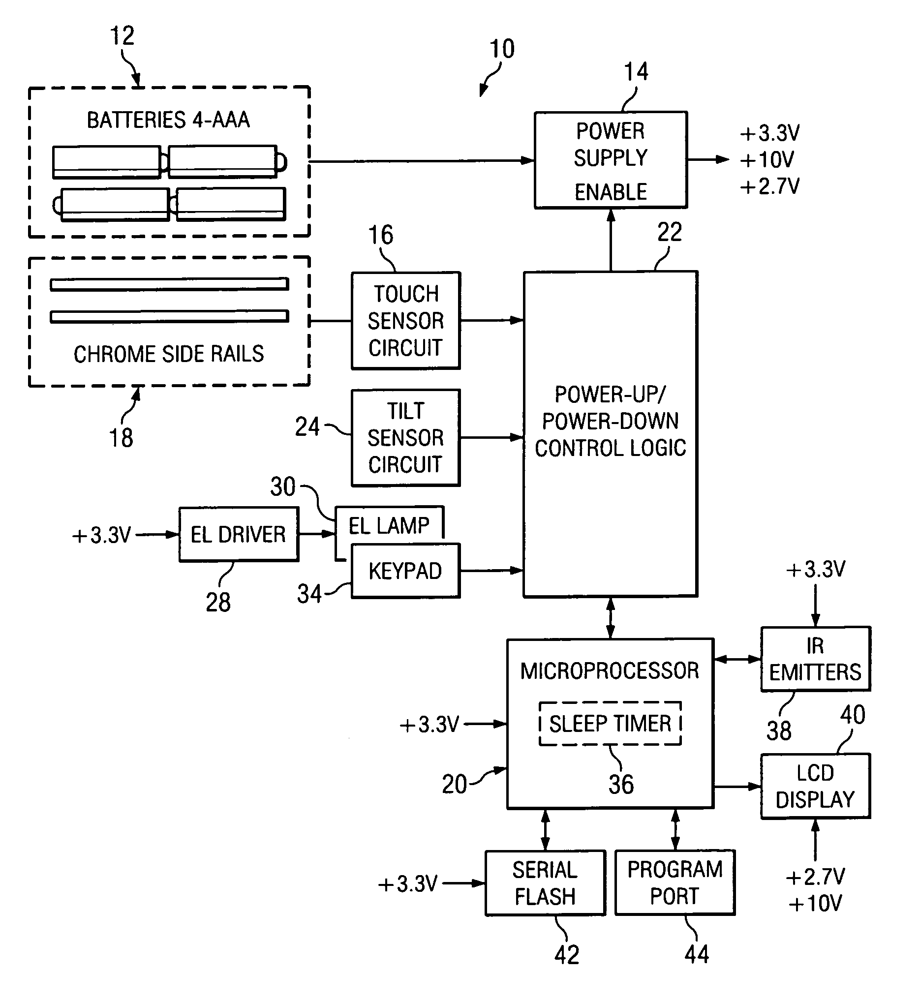
"The present invention is about a cordless electronic device with power management. It includes a power control circuit that can regulate power from a power source to a power consumption circuit. There is also a presence sensor that can detect the presence of a user and send a signal to the power control circuit to increase power to the device. The technical effect of this invention is to efficiently manage power consumption and provide better user experience for the cordless electronic device."

Problems solved by technology

The increased functionality and demands require greater power consumption, which results in greater power supply demand and reduced convenience and reliability because of the shorter intervals required between replacing or recharging batteries.
For example, certain ornamental designs (text size, color of text, color of text background) of remote controls make the button labels more difficult to read in daylight without backlight.
Backlighting, however, requires considerable power, which drastically reduces power source life before replacement or recharging.
This wastes precious real-estate on the remote control and is difficult for the user.
It is not uncommon for the tilt-sensor to get “stuck” such that more violent motion is required to turn on the backlight or for the tilt-sensor to register movement due to vibrations not related to the user picking up the remote.

Method used


Image

  • Power management for electronic devices
  • Power management for electronic devices
  • Power management for electronic devices

Examples


Embodiment Construction

[0018]Referring now to the drawings, wherein like reference numerals designate identical or corresponding parts throughout the several views, preferred embodiments of the present invention are described.

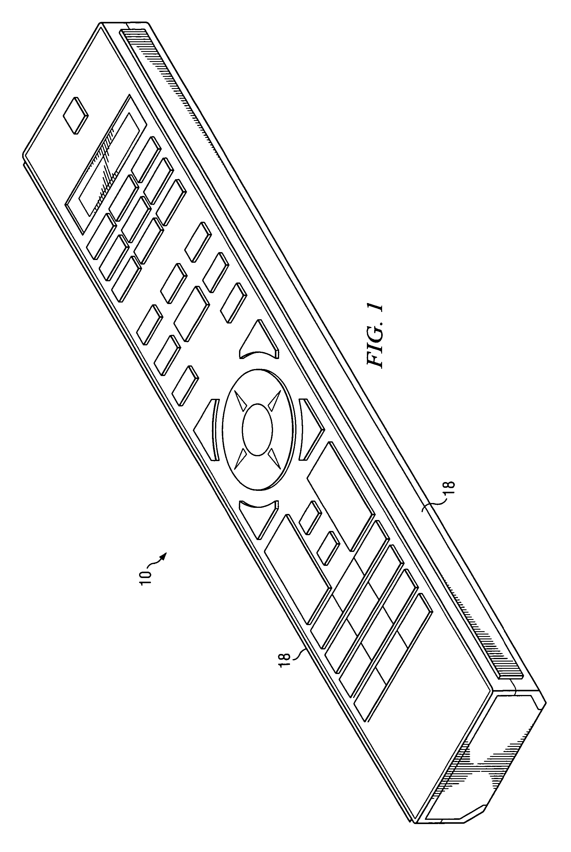
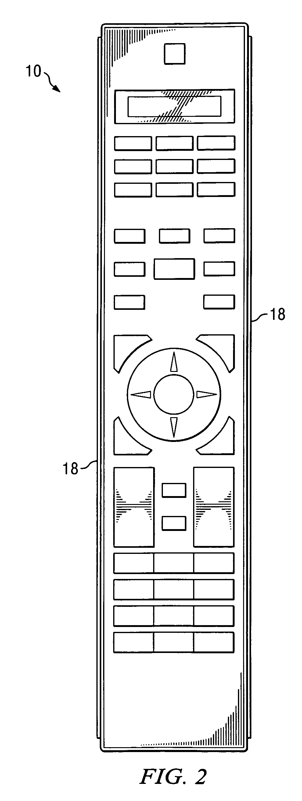
[0019]Referring to FIGS. 1 and 2, perspective and top views illustrating a remote control 10 with power management functionality according to one embodiment of the present invention is shown. The remote control 10 may include a plurality of buttons, keypad and / or other controls. The remote control 10 may be implemented with backlighting to assist with ease of use, especially in a low light conditions. The various buttons of the remote control 10 may be used in connection with a master controller to control any number of other electronic devices, or the remote control 10 may be used as a “universal remote control” to individually and directly control any number of devices, including, but not limited to, DVD players, CD player / recorders and VCR devices, along with virtually any other e...


PUM


Abstract

A cordless electronic device with power management system and method is provided that includes an outer surface, a power consumption circuit operable to consume power and for use in a cordless electronic device, a power supply circuit operable to regulate the power from a power source used to power the power consumption circuit of the cordless electronic device, a power control circuit operable to receive an input signal and to place the power consumption circuit in a lower or higher power state upon receipt of the input signal, a presence sensor operable to detect the presence of a user and to provide a presence sensor input signal to the power control circuit to place the power consumption circuit in the higher power state.

Description

CROSS REFERENCE TO RELATED APPLICATIONS[0001]Pursuant to 35 U.S.C. §119(e), the present document claims the benefit of the earlier filing date of co-pending U.S. provisional patent application Ser. No. 60 / 715,330, entitled “Remote Control with Power Management,” filed in the U.S. Patent and Trademark Office on Sep. 7, 2005, hereby incorporated by reference, having common inventors as the present document.BACKGROUND OF THE INVENTION[0002]1. Field of the Invention[0003]The present invention relates in general to power management and more particularly, but not by way of limitation, to power management for cordless electronic devices.[0004]2. Discussion of the Background[0005]Cordless electronic devices, including without limitation portable remote control devices, universal remotes, cell phones, telephones, PDAs, televisions, radios, media players, hand-held tools, scanners, GPS devices, electronic compasses and the like, are powered by a remote power supply, such as a battery, power c...

Claims


Application Information

Patent Timeline
Patent Type & Authority Patents(United States)
IPC IPC(8): H01H35/14
CPCH04B1/1615H04W52/0274Y02B60/50Y02D30/70
Inventor FARMER, MICHAEL SCOTTELLIS, VINCENT WILLIAMCARPENTER, KENNETH SCOTT
Owner HARMAN PROFESSIONAL INC
Learn More