
Data storage device

a data storage and data technology, applied in the field of data storage devices, can solve the problems of increasing the height of the ramp, affecting the and actuator mounting errors, etc., and achieve the effect of suppressing the deterioration of rigidity and dynamic characteristics of the tab

Inactive Publication Date: 2010-08-31
WESTERN DIGITAL TECH INC
View PDF15 Cites 0 Cited by
  • Summary
  • Abstract
  • Description
  • Claims
  • Application Information

AI Technical Summary

Benefits of technology

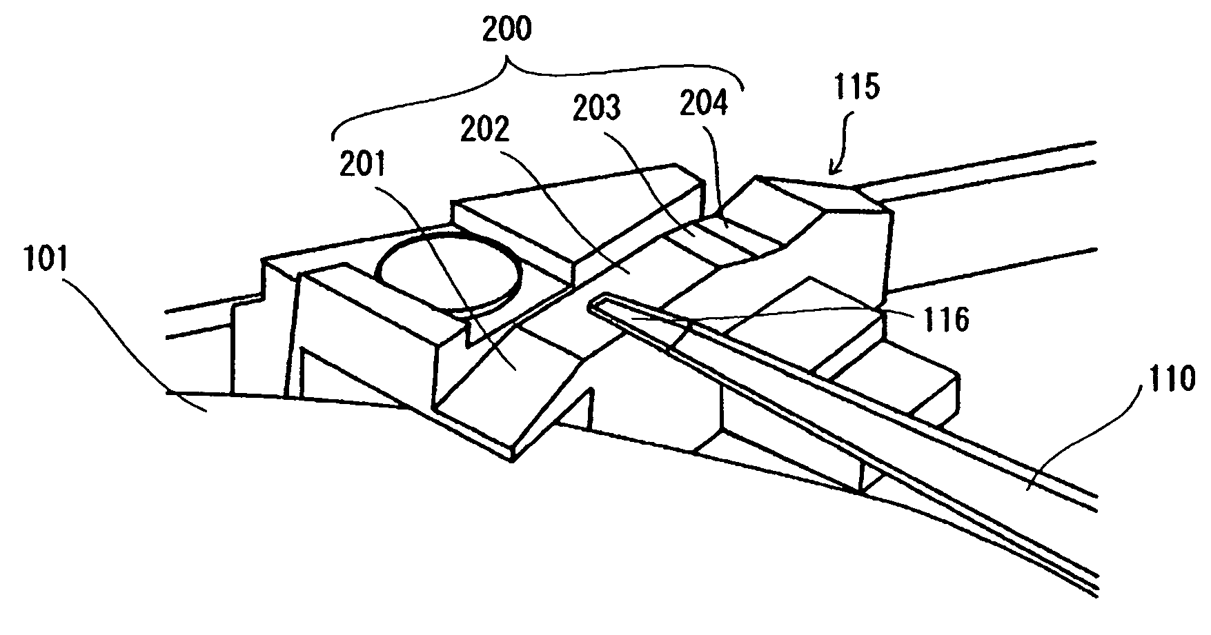
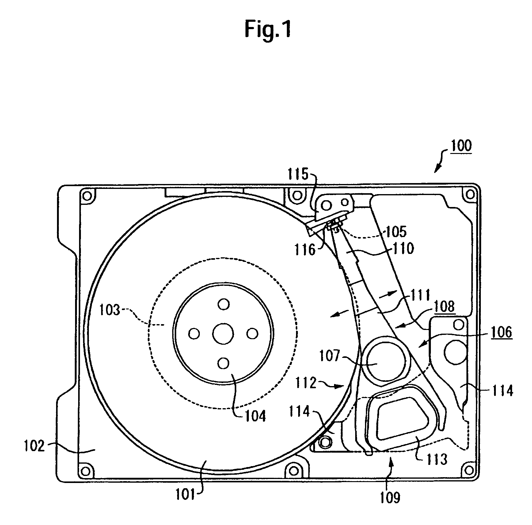
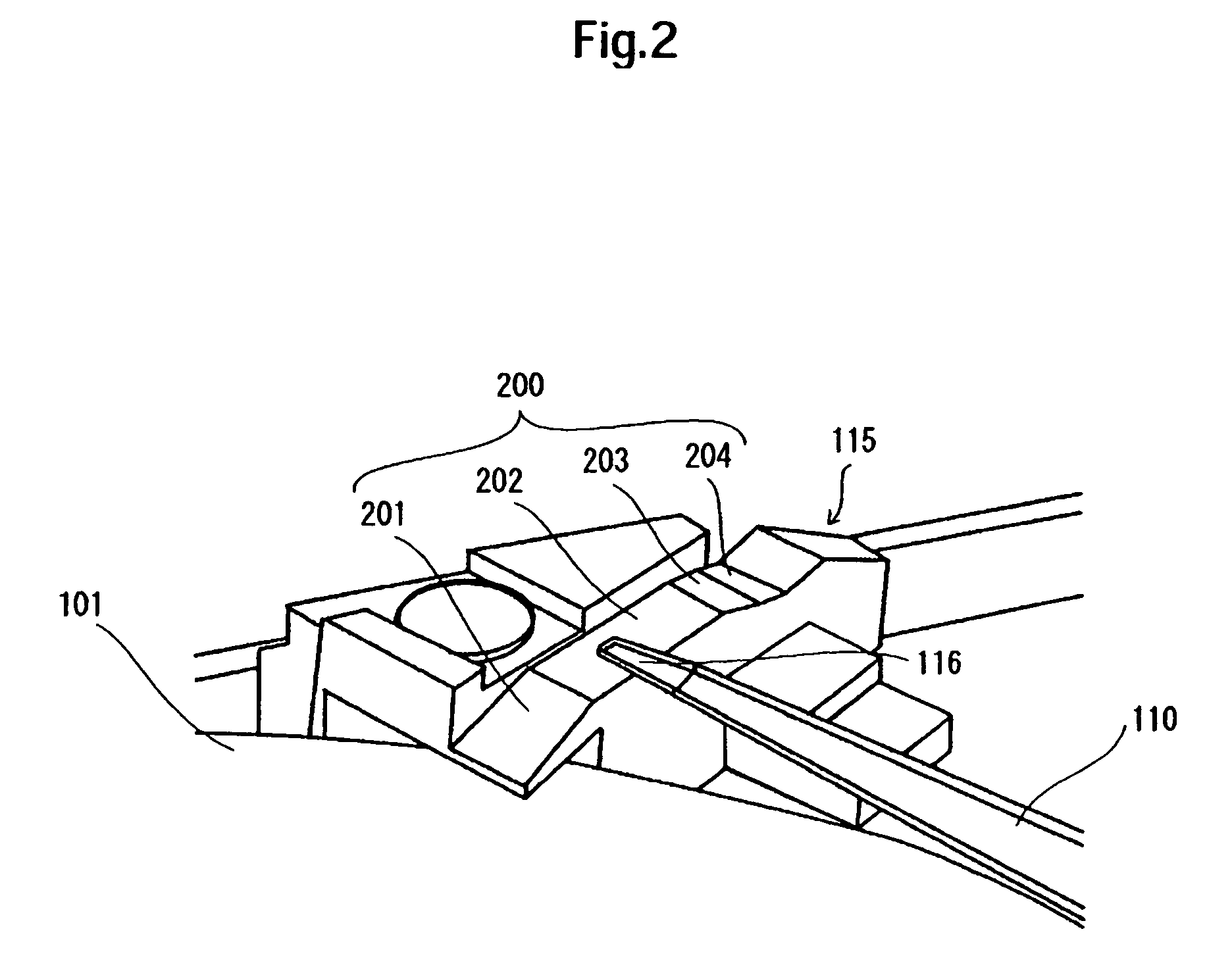
[0024]Embodiments in accordance with the present invention relate to suppressing the deterioration in rigidity and dynamic characteristics of a tab is to be suppressed even when an initial point of contact between a tab and a ramp during unloading is set closer to the outer periphery of a disk. Referring to the specific embodiments shown in FIGS. 1 and 3(a)-(c), a data storage device includes a head 105, a ramp 115 for unloading the head 105, a load beam 302 having a head support portion 302a for supporting the head 105 and a tab 116 adapted to slide on a sliding surface of the ramp 115 on a front end side with respect to the head support portion 302a, and an actuator 106 having the load beam 302 and adapted to actuate the head 105 for loading and unloading. During unloading, a portion of the tab 116 offset from the center in the transverse direction of the tab first comes into contact with the sliding surface of the ramp 115. The load beam 302 has a flange formed to be bent and continuously from the front end portion of the tab up to both ends of the head support portion.

Problems solved by technology

For example, errors of the ramp mounting position include an actuator mounting error and a ramp mounting error.
However, such an increased height of the ramp becomes a restriction on the thickness of the magnetic disk drive.
Moreover, since the length from the point of contact between the tab and the ramp up to the front end of the tab varies due to an error of the ramp mounting position, the height up to the front end of the tab is not constant in the state where the tab and the ramp are in contact with each other.
However, this does not intend to increase the memory capacity of a magnetic disk or reduce the thickness of a magnetic disk drive.
Besides, since the tab described in Patent Literature 1 extends as a plate tab to a front end of a load beam, it is apt to deflect upon contact of its projecting portion with the ramp, thus giving rise to a problem in point of rigidity of the tab.
If the tab is formed asymmetrically or the point of contact between the tab and the ramp is rendered oblique, a large vibration occurs due to a twist during loading or unloading, thus resulting in that dynamic characteristics of the suspension including the load beam are deteriorated markedly.
In this case, since the flange portion is provided only at the portion to be contacted with the ramp, it is impossible to prevent vibration caused by a twist during loading or unloading.
Therefore, the tab length and the recording area of the magnetic disk obtain restrictions due to an error of the ramp mounting position, thus giving rise to the problem that it is difficult to increase the memory capacity of the magnetic disk or reduce the thickness of the magnetic disk drive.
Moreover, in the conventional HDD, when the initial point of contact with the tab and the ramp during unloading is set outside the disk, the tab is made asymmetric, or the point of contact with the tab and the ramp is made oblique, or a flange portion is provided only at the portion of contact with the ramp, thus giving rise to the problem that the rigidity of the tab and dynamic characteristics of the suspension are deteriorated.

Method used


Image

  • Data storage device
  • Data storage device
  • Data storage device

Examples


Embodiment Construction

.

[0037]Embodiments in accordance with the present invention relate to a suspension and a data storage device using the same. More specifically, embodiments of the present invention relate to a suspension and a data storage device both suitable for a loading / unloading type hard disk drive.

[0038]It is an object of an embodiment of the present invention to reduce the influence of an error of the ramp mounting position in connection with the length of a tab and a recording area of a disk and thereby make it possible to increase the memory capacity and reduce the thickness of a disk drive. It is another object of an embodiment of the present invention to suppress deterioration of the tab rigidity and of dynamic characteristics even in the case where the initial point of contact between the tab and the ramp during unloading is set closer to the outer periphery of the disk.

[0039]In one embodiment of the present invention, a data storage device comprises a head adapted to access a recording...


PUM

PropertyMeasurementUnit
angleaaaaaaaaaa
sizeaaaaaaaaaa
widthaaaaaaaaaa

Abstract

Embodiments in accordance with the present invention relate to suppressing deterioration in rigidity and dynamic characteristics of a tab even when an initial point of contact between a tab and a ramp during unloading is set closer to the outer periphery of a disk. A data storage device in one embodiment of the present invention includes a head, a ramp for unloading the head, a load beam having a head support portion for supporting the head and a tab adapted to slide on a sliding surface of the ramp on a front end side with respect to the head support portion, and an actuator having the load beam and adapted to actuate the head for loading and unloading. During unloading, a portion of the tab offset from the center in the transverse direction of the tab first comes into contact with the sliding surface of the ramp. The load beam has a flange formed to be bent and continuously from the front end portion of the tab up to both ends of the head support portion.

Description

CROSS-REFERENCE TO RELATED APPLICATION[0001]The instant nonprovisional patent application claims priority to Japanese Patent Application 2006-060045, filed Mar. 6, 2006 and incorporated by reference in its entirety herein for all purposes.BACKGROUND OF THE INVENTION[0002]The devices using an optical disk, a magnetic tape, or other forms of media are known as data storage devices. Among them, a hard disk drive (HDD) is commonly used as a storage device for a computer, and the HDD is one of storage devices essential for computer systems which are currently used. In addition, the use of the HDD are not only limited to computer systems but also has widely expanded because of the superior characteristics. The HDDs are used, for example, for moving picture recording / reproducing devices, car navigation systems, cellular phones, removable memories used for digital cameras and the like.[0003]The HDD is provided with a magnetic disk for storing data and a head for writing and / or reading out d...

Claims


Application Information

Patent Timeline
Patent Type & Authority Patents(United States)
IPC IPC(8): G11B5/54
CPCG11B5/54
Inventor DEGUCHI, TAKAAKIOHTA, MUTSUROTSUDA, SHINGONAKAMURA, TAICHI
Owner WESTERN DIGITAL TECH INC
Learn More