Pneumatic tire

a pneumatic tire and tire body technology, applied in the field of pneumatic tires, can solve the problems of large distance between the outer surface of the carcass and the outer surface of the protruding portion, the rigidity and cut resistance of the pneumatic tire may deteriorate, and the air resistance at the maximum width position of the tire tends to become large, so as to achieve the effect of reducing the fuel efficiency of the vehicle, and reducing the air resistance of the vehicl

Active Publication Date: 2022-05-10
YOKOHAMA RUBBER CO LTD
View PDF15 Cites 0 Cited by
  • Summary
  • Abstract
  • Description
  • Claims
  • Application Information

AI Technical Summary

Benefits of technology

[0023]As a result, the air resistance of the vehicle is further reduced, and the fuel efficiency of the vehicle is thus improved. As a result of the recessed portions being provided in addition to the protrusion portions, the air flowing from the front side to the rear side of the vehicle becomes turbulent. As a result, a turbulent flow boundary layer is generated in the periphery of the pneumatic tire, and an expansion of the air is suppressed. As a result of the expansion of the air passing the vehicle being suppressed, the air resistance of the vehicle is reduced, and the fuel efficiency of the vehicle is thus improved.
[0024]According to an aspect of the present technology, provided is a pneumatic tire that achieves weight reduction while suppressing deterioration in rigidity and cut resistance of the pneumatic tire.

Problems solved by technology

Due to the weight reduction of the pneumatic tire, there is a possibility that rigidity and cut resistance of the pneumatic tire may deteriorate.
Further, when a vehicle on which the pneumatic tires are mounted travels, air resistance at the tire maximum width position tends to become large.
When W1 / W3 is smaller than 0.80, the distance between the carcass outer surface and the protrusion portion outer surface becomes too large, and the weight reduction of the pneumatic tire becomes difficult.
When G1 / G2 is smaller than 0.1, the thickness of the side rubber becomes too thin, and the carcass is not sufficiently protected.
When G1 / G2 is larger than 1, the thickness of the side rubber becomes larger than the height of the protrusion portion, and the weight reduction of the pneumatic tire becomes difficult.
Thus, the carcass 2 is not sufficiently protected.
Consequently, the weight of the pneumatic tire simply increases, while no significant improvement in functions of the protrusion portions (namely, a rigidity reduction suppression function, a cut resistance reduction suppression function, and a carcass protection function) is expected.
When the number of protrusion portions is more than 50, the protrusion portions themselves become a source of air resistance, and the air distribution promotion effects and the air streamlining effects are not sufficiently obtained.
Further, when the number of protrusion portions is too large, the weight of the pneumatic tire increases.
When the short-direction maximum width of the protrusion portion is less than 0.5 mm, the protrusion portion easily deforms and becomes difficult to obtain the air distribution promotion effect and the air streamlining effect.
When the short-direction maximum width of the protrusion portion is greater than 5.0 mm, the protrusion portion itself becomes a source of air resistance, and the air distribution promotion effect and the air streamlining effect are not sufficiently obtained.
Further, when the protrusion portion is too thick, the weight of the pneumatic tire increases.
As a result of the recessed portions being provided in addition to the protrusion portions, the air flowing from the front side to the rear side of the vehicle becomes turbulent.

Method used


Image

  • Pneumatic tire
  • Pneumatic tire
  • Pneumatic tire

Examples


first embodiment

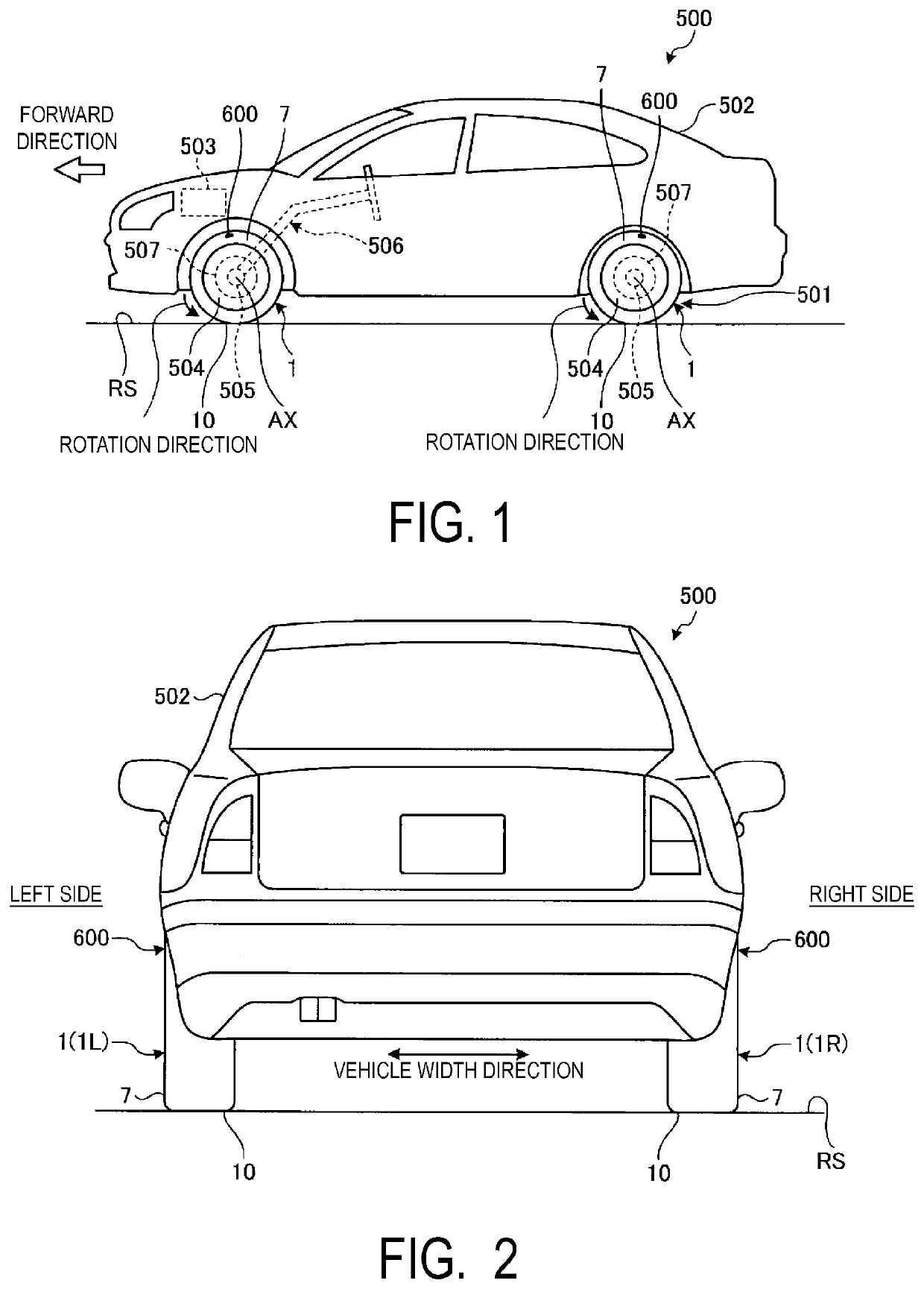
[0063]A first embodiment will now be described. FIG. 1 is a side view illustrating an example of a vehicle 500 according to the present embodiment. FIG. 2 is a rear view of the vehicle 500 according to the present embodiment. Tires 1 are mounted on the vehicle 500. The tires 1 are pneumatic tires. The tires 1 mounted on the vehicle 500 rotate about a rotation axis AX and travel on a road surface RS.

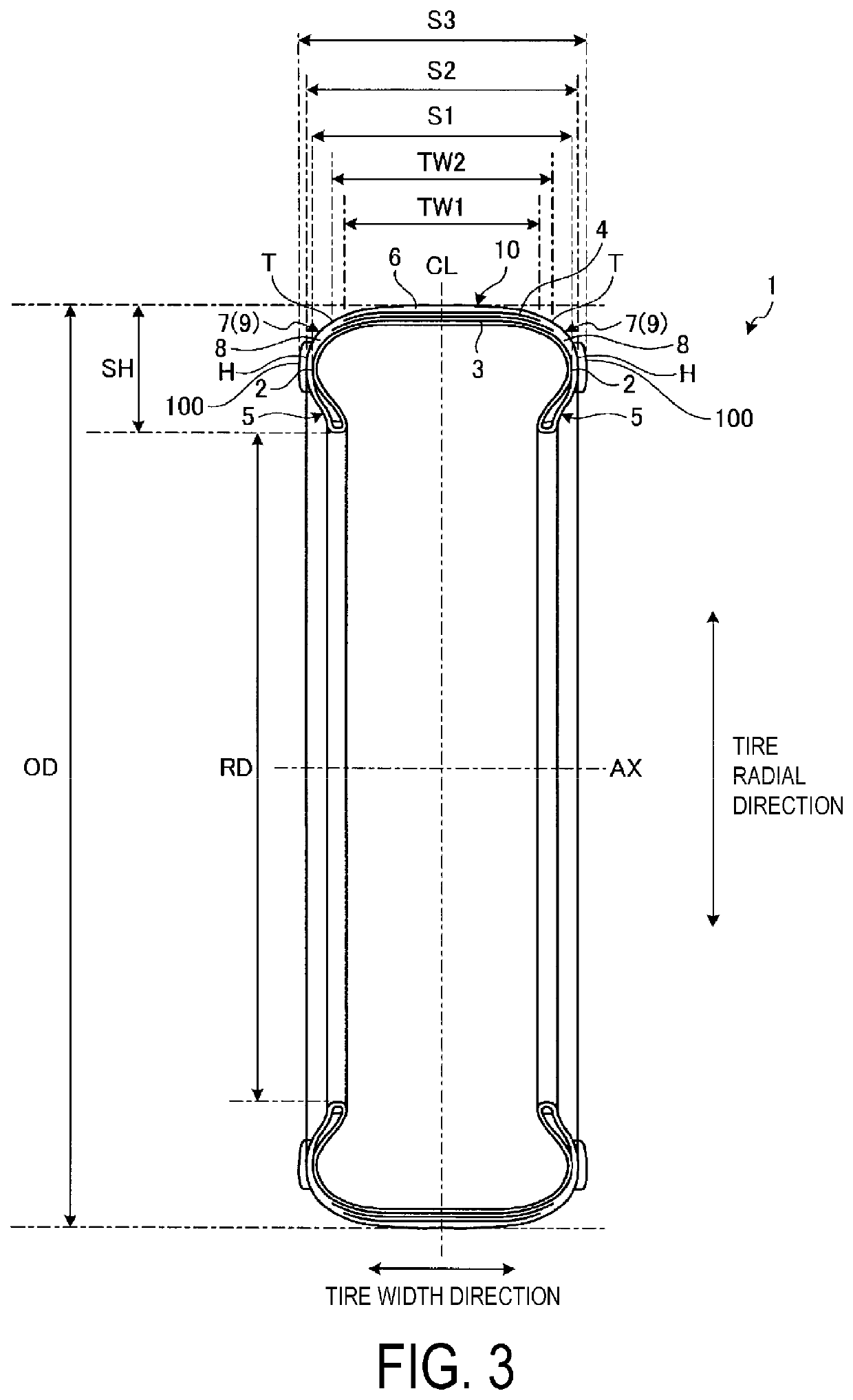
[0064]Herein, a tire circumferential direction, a tire radial direction, and a tire width direction will be used as terms to explain the positional relationships between the components. The tire circumferential direction refers to a rotation direction about the rotation axis AX of the tire 1. The tire radial direction refers to a radiation direction out from the rotation axis AX of the tire 1. The tire width direction refers to a direction parallel with the rotation axis AX of the tire 1.

[0065]As illustrated in FIG. 1 and FIG. 2, the vehicle 500 is provided with a driving apparatus 501 th...

modified examples

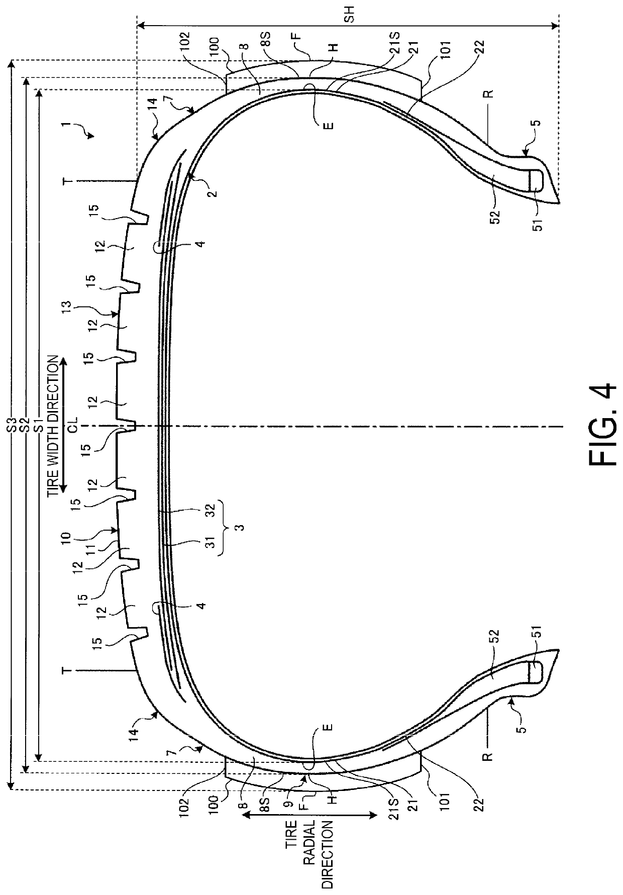
[0121]In the tire 1 provided with the protrusion portions 100, the distance W1, the distance W2, and the distance W3 may be set so as to satisfy the following conditions:

0.80≤W1 / W3≤0.95  (3); and

1.0 mm≤G1≤2.5 mm  (4).

[0122]When the condition (3) is satisfied, the weight reduction of the tire 1 is achieved while suppressing the deterioration in the rigidity and the cut resistance of the tire 1.

[0123]Further, when the condition (4) is satisfied, the weight reduction of the tire 1 is achieved while sufficiently protecting the carcass 2. A side rubber gage of a conventional tire is thicker than 2.5 mm. As a result of causing the distance G1 to be 2.5 mm or less through making it smaller than a conventional side rubber gage, the weight reduction of the tire 1 is achieved. When the distance G1 is smaller than 1.0 mm, the thickness of the side rubber 8 becomes too thin, and the carcass 2 is not sufficiently protected. As a result of the conditions (3) and (4) being satisfied, the weight re...

second embodiment

[0124]FIG. 8 is a diagram schematically illustrating the side surface 8S provided with the protrusion portions 100 according to the present embodiment. FIG. 9 is an enlarged view of a part of FIG. 8. As illustrated in FIG. 8 and FIG. 9, the protrusion portions 100 are inclined with respect to the radiating line LR from the rotation axis AX such that the first end portion 101 and the second end portion 102 have different positions from each other in the tire circumferential direction. In the example illustrated in FIG. 8 and FIG. 9, 12 protrusion portions 100 are provided.

[0125]Further, for each of the plurality of protrusion portions 100, directions in which the second end portions 102 are shifted with respect to the first end portions 101 are the same. Specifically, the inclination directions of the plurality of protrusion portions 100 are the same.

[0126]As a result of the longitudinal-shape protrusion portions 100 being disposed in the inclined manner, the carcass 2 is sufficientl...


PUM


Abstract

A tire has a tire center in the tire width direction. An intersection point of a carcass outer surface with a parallel line extending parallel with a rotation axis and passing through a tire maximum width position is denoted as P1. An intersection point of the parallel line LP with a side surface is denoted as P2. An intersection point of the parallel line with a protrusion portion outer surface of a protrusion portion is denoted as P3. A distance between the tire center and the intersection point P1 is denoted as W1. A distance between the tire center and the intersection point P3 is denoted as W3. A distance between the intersection point P1 and the intersection point P2 is denoted as G1. A distance between the intersection point P2 and the intersection point P3 is denoted as G2. 0.80≤W1/W3≤0.95 and 0.1≤G1/G2≤1.

Description

TECHNICAL FIELD[0001]The present technology relates to a pneumatic tire.BACKGROUND ART[0002]In a technical field relating to a pneumatic tire, development has been promoted to reduce the weight and rolling resistance of the pneumatic tire, in order to improve the fuel efficiency of a vehicle. Japanese Unexamined Patent Application Publication No. 2012-091731 discloses a technology that is designed to reduce the weight and rolling resistance of the pneumatic tire by extending a carcass folded back portion up to a point between a belt and a carcass main body portion, and consequently reducing the size of a rubber gage in a side portion.SUMMARY[0003]Due to the weight reduction of the pneumatic tire, there is a possibility that rigidity and cut resistance of the pneumatic tire may deteriorate. Thus, there is a demand for development of a pneumatic tire that achieves the weight reduction while suppressing the deterioration in the rigidity and the cut resistance.[0004]The present technolo...

Claims


Application Information

Patent Timeline
Patent Type & Authority Patents(United States)
IPC IPC(8): B60C13/02B60C3/04B60C13/00
CPCB60C13/02B60C3/04B60C2013/007Y02T10/86
Inventor KURIYAMA, MASATOSHI
Owner YOKOHAMA RUBBER CO LTD
Why Eureka
Try Eureka