Control system designed to minimize deterioration of exhaust gas sensor for use in diesel engine

Inactive Publication Date: 2007-06-14
DENSO CORP
View PDF5 Cites 0 Cited by
  • Summary
  • Abstract
  • Description
  • Claims
  • Application Information

AI Technical Summary

Benefits of technology

[0010] It is therefore a principal object of the invention to provide a diesel engine exhaust gas sensor control system designe

Problems solved by technology

However, when the air-fuel ratio sensor is warmed by the heater in the presence of drops of water in the exhaust system, it may result in adhesion of the drops of water to the body of the air-fuel ratio sensor, thereby causing physical damage to thereto.
When the air-fuel ratio sensor is not warmed up, it may cause the air-fuel ratio sensor to be ex

Method used


Image

  • Control system designed to minimize deterioration of exhaust gas sensor for use in diesel engine
  • Control system designed to minimize deterioration of exhaust gas sensor for use in diesel engine
  • Control system designed to minimize deterioration of exhaust gas sensor for use in diesel engine

Examples


first embodiment

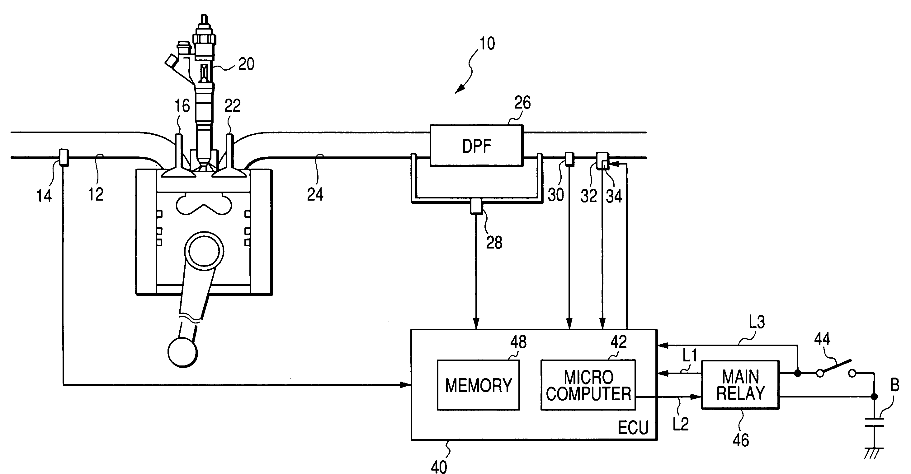
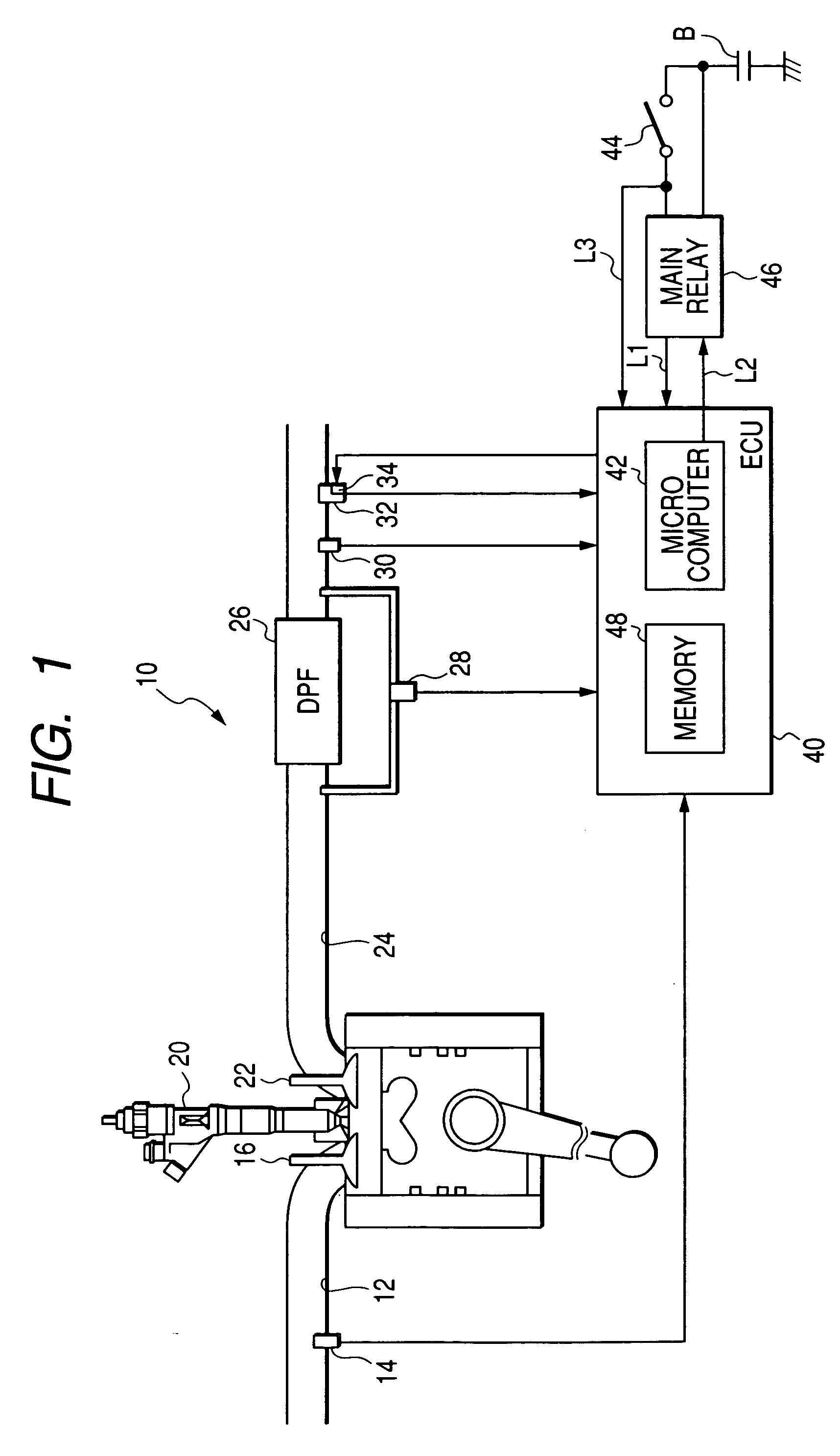
[0033] Referring to the drawings, wherein like reference numbers refer to like parts in several views, particularly to FIG. 1, there is shown an automotive engine control system according to the invention which is designed as, for example, a common rail fuel injection system (also called an accumulator injection system) working to control injection of fuel into an internal combustion diesel engine 10.

[0034] The diesel engine 10 connects with an intake pipe 12 and an exhaust pipe 24. The intake pipe 12 has installed therein an intake air temperature sensor 14 working to measure the temperature of intake air sucked into the intake pipe 12. The intake air is charged by opening the an intake valve 16 into a combustion chamber 18 of the engine 10. The intake air is mixed with fuel sprayed by a fuel injector 20 and then burned in the combustion chamber 18. The burned mixture is emitted as exhaust gas to the exhaust pipe 24 when an exhaust valve 22 is opened.

[0035] The exhaust pipe 24 has...

second embodiment

[0061]FIG. 11 shows the exhaust gas temperature control program according to the invention which is a modification of the one in FIG. 8. This program is initiated upon turning on of the ignition switch 44.

[0062] After entering the program, the routine proceeds to step 60 wherein an output of the intake air temperature sensor 14 is sampled to determine the temperature of air changed into the engine 10. The routine proceeds to step 62 wherein it is determined whether the temperature of the intake air, as derived in step 60, is lower than or equal to a preselected value β or not. This determination is made for determining whether the temperature of the air-fuel ratio sensor 32 is lower than that of the exhaust gas or not. Usually, immediately after start-up of the engine 10, the temperature of the intake air is substantially identical with that of the outside air. Therefore, the lower the temperature of the intake air, the longer a period of time for which the temperature of the air-fu...

third embodiment

[0063] The engine control system according to the invention will be described below which is designed to monitor whether the temperature of the exhaust gas has exceeded a predetermined level or not during each trip between turning on and off of the ignition switch 44 and, when the number of the consecutive trips each for which the temperature of the exhaust gas was kept below the predetermined level exceeds a given value, executes the post injection during a subsequent trip of the vehicle.

[0064]FIG. 12 illustrates a counting program to be performed by the ECU 40 upon turning on of the ignition switch 44 to count the number of the consecutive trips each for which the temperature of the exhaust gas is kept below a given value.

[0065] After entering the program, the routine proceeds to step 70 wherein an output of the exhaust gas temperature sensor 30 is sampled to determine the temperature of the exhaust gas flowing in the exhaust pipe 24.

[0066] The routine proceeds to step 72 wherei...


PUM


Abstract

A gas sensor control apparatus for an exhaust gas sensor working to measure a selected component of exhaust gas from a diesel engine. The apparatus consists of a heater to heat the exhaust gas sensor to activate it and a controller working to restrict an operation of the heater in the condition that drops of water are expected to exist in an exhaust system of the engine. The controller determines whether the condition in which the temperature of the exhaust gas sensor is expected to be lower than that of the exhaust gas is met or not based on an operating condition of the diesel engine. When the temperature condition is met, the controller elevates the temperature of the exhaust gas to promote heating of the exhaust gas sensor through the heater, thereby minimizing the deterioration in characteristics or performance of the exhaust gas sensor.

Description

CROSS REFERENCE TO RELATED DOCUMENT [0001] The present application claims the benefit of Japanese Patent Application No. 2005-356123 filed on Dec. 9, 2005, the disclosure of which is incorporated herein by reference. BACKGROUND OF THE INVENTION [0002] 1. Technical Field of the Invention [0003] The present invention relates generally to a diesel engine exhaust gas sensor control system designed to control operations of an exhaust gas sensor and a heater working to heat the exhaust gas sensor to activate it, and more particularly to such a control system designed to minimize the deterioration in operation of the exhaust gas sensor. [0004] 2. Background Art [0005] It is known to use an air-fuel ratio sensor to measure the air-fuel ratio of exhaust gas flowing in an exhaust system of a gasoline engine in order to control an output of the engine. In use, the air-fuel ratio sensor is typically warmed up by a heater to ensure the stability in operation thereof. However, when the air-fuel r...

Claims


Application Information

Patent Timeline
IPC IPC(8): G01N27/26
CPCF01N2560/02F02D41/029F02D41/1446F02D41/1494F02D41/405F02D2200/0418G01N27/4065Y02T10/44Y02T10/40
Inventor KOSAKA, YUJI
Owner DENSO CORP
Why Eureka
Try Eureka