Inverter circuit with switch circuit having two transistors operating alternatively

a switch circuit and inverter circuit technology, applied in the field of inverter circuits, can solve problems such as the risk of first chip or second chip burning ou

Active Publication Date: 2010-08-31
INNOLUX CORP +1
View PDF18 Cites 160 Cited by
  • Summary
  • Abstract
  • Description
  • Claims
  • Application Information

AI Technical Summary

Benefits of technology

[0013]When one of the transistors 121, 122, 131, 132 is turned on, the corresponding transistor 121, 122, 131, 132 has a saturation resistance. Heat is correspondingly generated in the corresponding transistor 121, 122, 131, 132 when the current flows through one of the transistors 121, 122, 131, 132. According to the above description, the first transistor 121 and the second transistor 122 are turned on or turned off simultaneously and the third transistor 131 and the fourth transistor 132 are turned on or turned off simultaneously. When the first transistor 121 and the second transistor 122 are turned on simultaneously, a great deal of heat is generated in the first chip. When the third transistor 131 and the fourth transistor 132 are turned on simultaneously, a great deal of heat is generated in the second chip. When the inverter circuit 1 operates for a long time, the heat generated in the first chip or in the second chip can not dissipate quickly and accumulates in the first chip or in the second chip. Thus, the first switch circuit 12 or the second switch circuit 13 may be impaired or even damaged, the first chip or the second chip are liable to be burned out.

Problems solved by technology

Thus, the first switch circuit 12 or the second switch circuit 13 may be impaired or even damaged, the first chip or the second chip are liable to be burned out.

Method used


Image

  • Inverter circuit with switch circuit having two transistors operating alternatively
  • Inverter circuit with switch circuit having two transistors operating alternatively
  • Inverter circuit with switch circuit having two transistors operating alternatively

Examples


Embodiment Construction

[0020]Reference will now be made to the drawings to describe various embodiments of the present invention in detail.

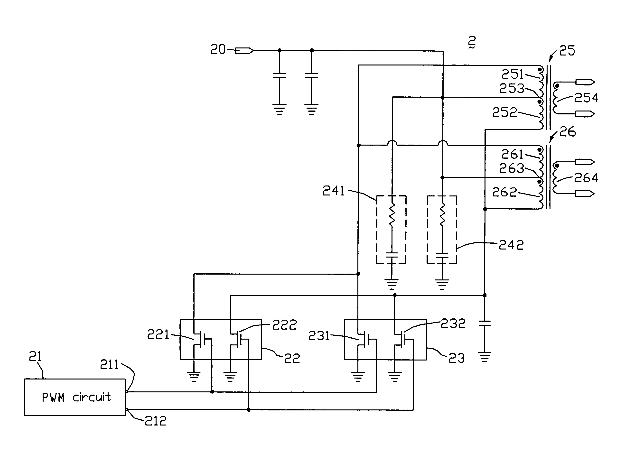
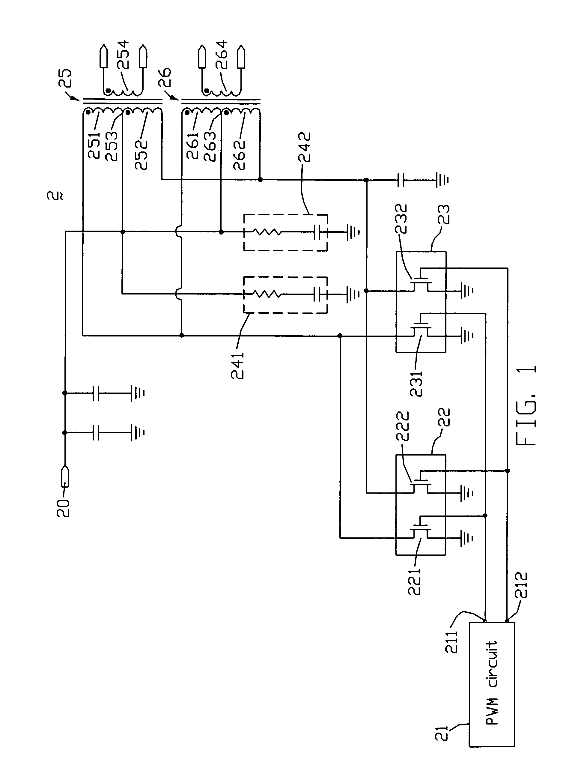
[0021]FIG. 1 is a circuit diagram of an inverter circuit of the present invention. The inverter circuit 2 includes a DC input terminal 20 connected to a DC power supply (not shown), a PWM circuit 21, a first switch circuit 22, a second switch circuit 23, a first filter circuit 241, a second filter circuit 242, a first transformer 25, and a second transformer 26. The DC input terminal 20 is connected to ground via a capacitor (not labeled).

[0022]The PWM circuit 21 includes a first output port 211 and a second output port 212. The first output port 211 is used to output a first square wave signal, and the second output port 212 is used to output a second square wave signal. Phases of the two square wave signals are opposite.

[0023]The first switch circuit 22 includes a first transistor 221 and a second transistor 222. The transistors 221 and 222 are NMOSFETs. A gate elect...


PUM


Abstract

An exemplary inverter circuit (2) includes a first switch circuit (22) including a first transistor (221) and a second transistor (222); a second switch circuit (23) including a third transistor (231) and a fourth transistor (232); and a pulse width modulation circuit (21) including a first output terminal (211) and a second output terminal (212). A gate electrode of the first transistor is connected to the first output port. A gate electrode of the second transistor is connected to the second output port. A gate electrode of the third transistor is connected to the first output port. A gate electrode of the fourth transistor is connected to the second output port. A drain electrode of the third transistor is connected to a drain electrode of the first transistor, and a drain electrode of the fourth transistor is connected to a drain electrode of the second transistor.

Description

FIELD OF THE INVENTION[0001]The present invention relates to inverter circuits, and particularly to an inverter circuit with switch circuits, each of the switch circuits includes two transistors operating alternatively.GENERAL BACKGROUND[0002]In general, a liquid crystal display (LCD) device needs to have an inverter circuit installed therein, for converting an external direct current (DC) voltage into an alternating current (AC) voltage.[0003]FIG. 2 is a circuit diagram of a conventional inverter circuit. The inverter circuit 1 includes a DC input terminal 10 connected to a DC power supply (not shown), a pulse width modulation (PWM) circuit 11, a first switch circuit 12, a second switch circuit 13, a first filter circuit 141, a second filter circuit 142, a first transformer 15, and a second transformer 16.[0004]The PWM circuit 11 includes a first output port 111 and a second output port 112. The first output port 111 is used to output a first square wave signal, and the second outp...

Claims


Application Information

Patent Timeline
Patent Type & Authority Patents(United States)
IPC IPC(8): H02M7/538
CPCH02M7/5381H02M2001/009H02M1/009
Inventor LU, JIAN-HUIZHOU, TONG
Owner INNOLUX CORP
Why Eureka
Try Eureka