
Grid-holding element

a technology of holding element and grid, which is applied in the direction of building scaffolds, candle holders, sewerage structures, etc., can solve the problems of not being able to directly mount, using a hand-held setting tool, and being unable to secure a grid to a support or constructional component without using some auxiliary means, so as to achieve the optimal shape of the holding element, increase the tolerance range, and increase the height difference

Active Publication Date: 2010-09-07
HILTI AG
View PDF16 Cites 46 Cited by
  • Summary
  • Abstract
  • Description
  • Claims
  • Application Information

AI Technical Summary

Benefits of technology

[0010]The foregoing novel features of the present invention insure that the holding element can easily be secured on a support with a setting tool and that the holding element height has a certain tolerance range. At the same time, any auxiliary elements become unnecessary.
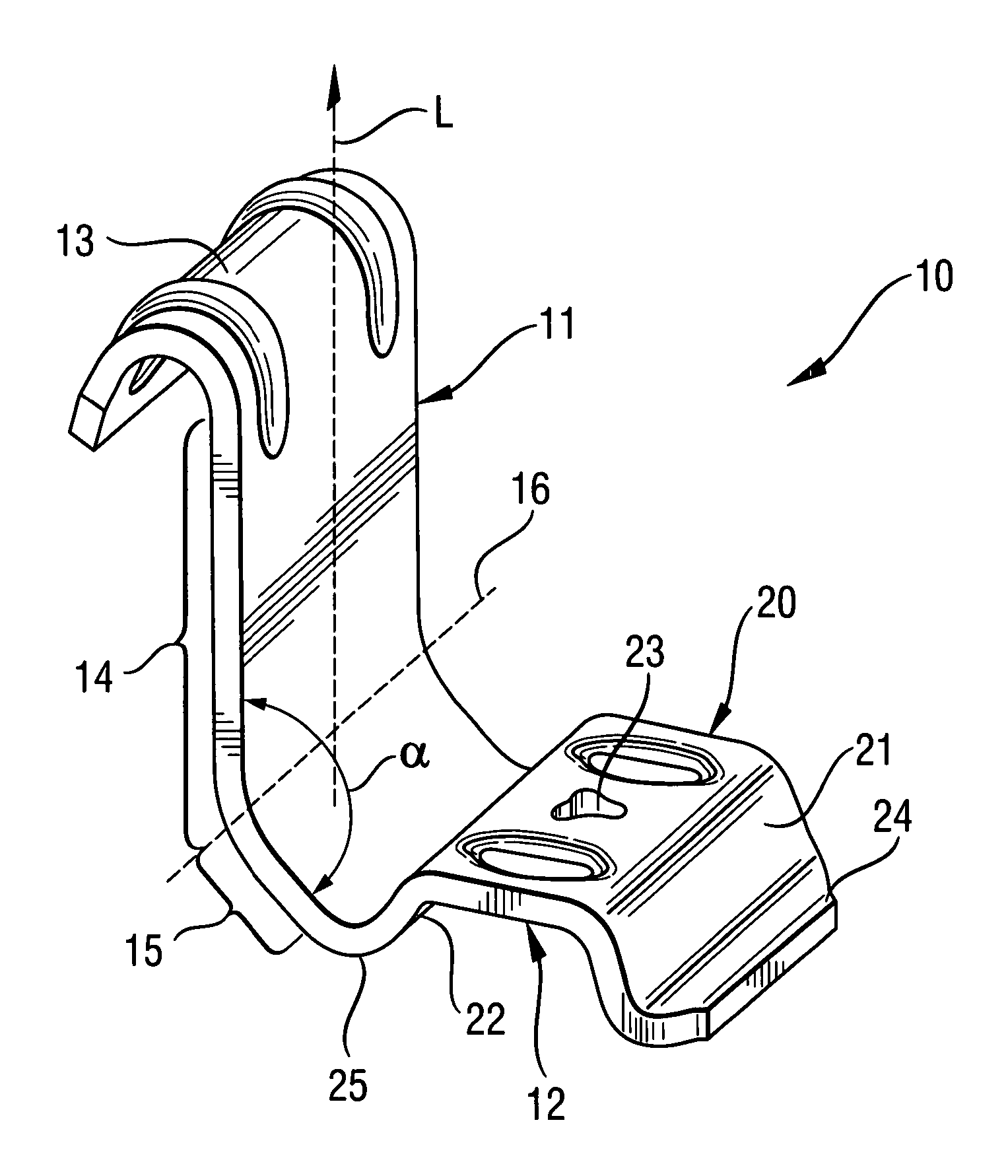
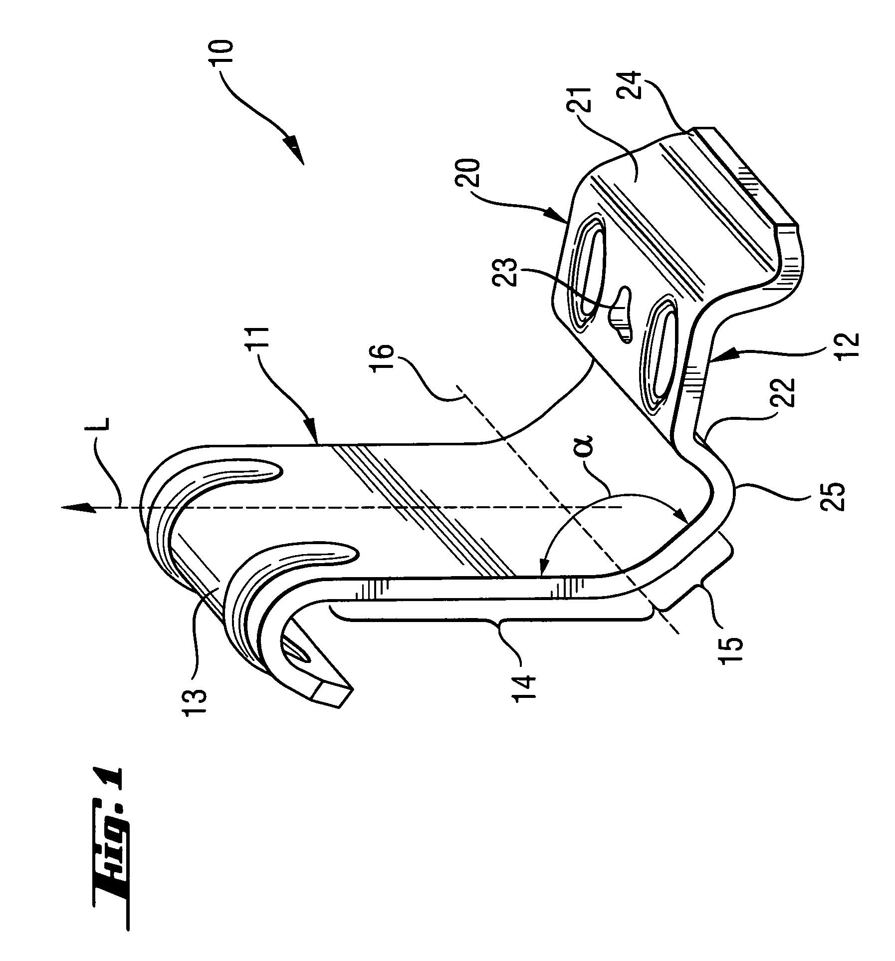
[0013]Advantageously, the first leg has a first surface section and at least one second surface section forming an angle with the first surface section, a bending axis between the two surface sections extends transverse to a longitudinal extent of the first leg. The angle between the surface sections can be acute or obtuse. As a result, both surface section act as a springy hinge, with surface sections pulling away form each other under a heavy load. This further increases the tolerance range, without increasing the height difference between the two foot sections of the attachment section. An optimal shape of the holding element is achieved when the angle between two surface sections amounts from 125° to 150°.

Problems solved by technology

The drawbacks of the holding element of U.S. Pat. No. 5,118,147 consists in that it can only be used with a plate-shaped element as a counter-support, and it cannot be directly mounted, e.g., using a hand-held setting tool.
The drawback of the holding element of U.S. Pat. No. 4,703,833 consists in that it is impossible to secure a grid to a support or constructional component, without using some auxiliary means.

Method used


Image

  • Grid-holding element
  • Grid-holding element
  • Grid-holding element

Examples


Embodiment Construction

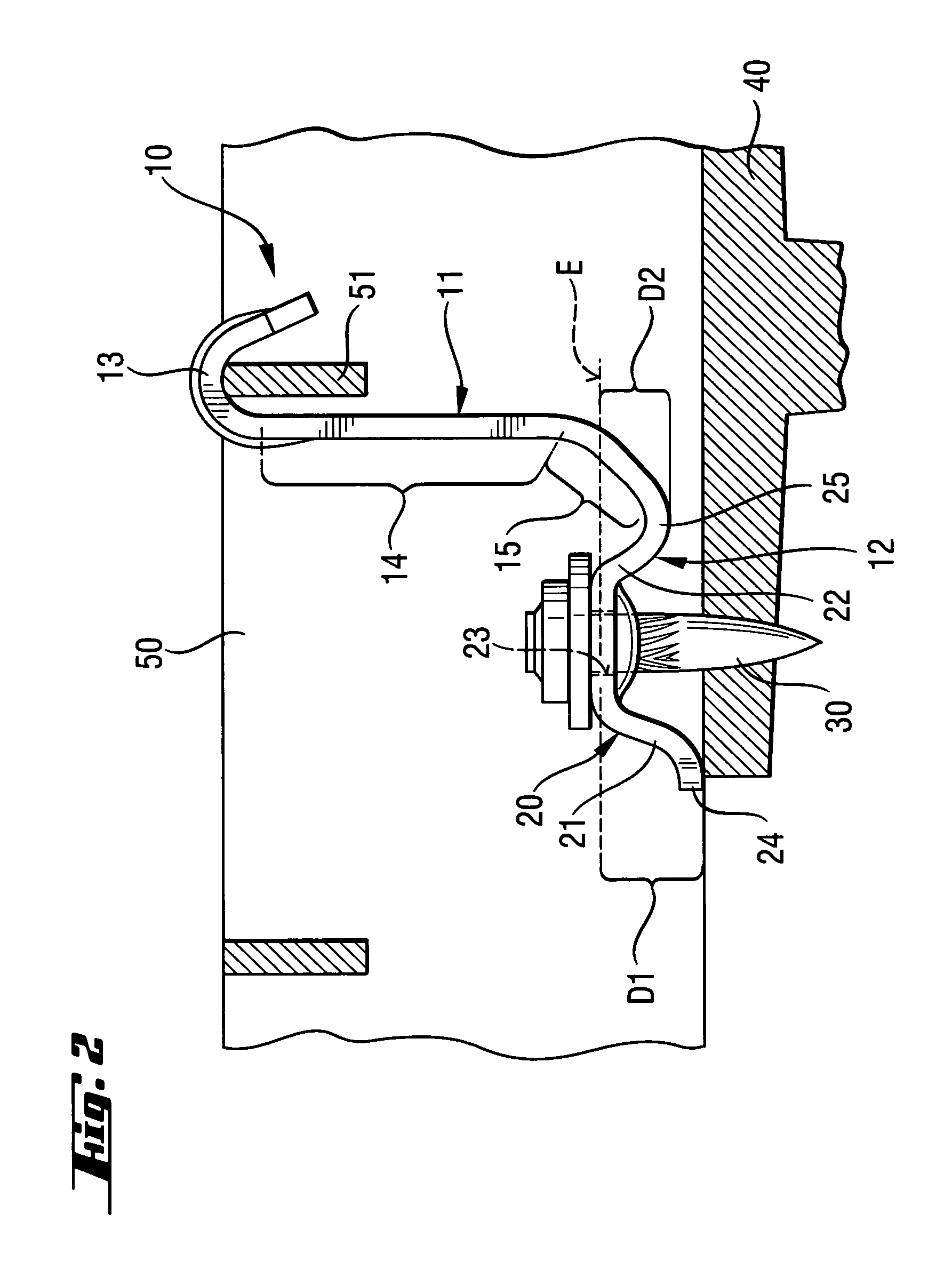
[0019]A grid-holding element 10 according to the present invention, which is shown in FIGS. 1-2, has a first leg 11 and a second leg 12 which are arranged approximately at a right angle to each other. The first leg 11 has a hook-shaped free upper end 13 for engaging around a strut 51 of a grid 50 or another element to-be-secured on a support 40. The first leg 11 further has first and second surface sections 14 and 15 that extend to each other in the initial, not secured position of the holding element 10, at an angle α of about 138°. However, in the embodiment shown in the drawings and having two surface sections 14, 15, a greater or smaller angle α that can vary in a range from 125° to 150° can be provided. The first leg 11 extends substantially in a longitudinal direction L that is directed substantially perpendicular to a bending axis 16 along which both surface sections 14, 15 abut each other.

[0020]The second leg 12 forms a saddle-shaped attachment section 20 that has a through-...


PUM


Abstract

A grid holding element has a first leg (11) at least one free end of which is hook-shaped, and a second leg (12) having a saddle-shaped attachment section (20) in which a through-opening (23) through which a fastening element (30) is extendable, is formed, a first foot section (2) that projects from the attachment section in a direction away from the first leg (11), and a second foot section (22) adjoining the first leg (11), with a maximal extension length (D1) of the first foot section (21) in a direction perpendicular to a plane (E) defined by the attachment section (20), being greater than a maximal extension length (D2) of the second foot section (22) in the direction perpendicular to the plane (E).

Description

BACKGROUND OF THE INVENTION[0001]1. Field of the Invention[0002]The present invention relates to a grid-holding element having a first leg at least one free end of which is hook-shaped and a second leg having an attachment section provided with a through-opening through which a fastening element such as, e.g., nail or bolt, is extendable.[0003]2. Description of the Prior Art[0004]U.S. Pat. No. 5,118,147 discloses a grid-holding element of the type described above and the hook-shaped end of which engages a support, and the end of which remote from the hook-shaped end has an engagement area for a screw. The screw connects the holding element with a plate-shaped element that lies on a grid which is secured to the support upon tightening the holding element.[0005]The drawbacks of the holding element of U.S. Pat. No. 5,118,147 consists in that it can only be used with a plate-shaped element as a counter-support, and it cannot be directly mounted, e.g., using a hand-held setting tool.[000...

Claims


Application Information

Patent Timeline
Patent Type & Authority Patents(United States)
IPC IPC(8): A47F5/00A47H1/10
CPCF16B2/02Y10T292/20E04C2/428F16B5/0685E03F5/06
Inventor DURIG, MARKUSFOSER, THOMAS
Owner HILTI AG
Learn More