Pothead for use in highly severe conditions

a pothead and high temperature technology, applied in the field of subterranean connectors, can solve the problems of large profile, large pothead design, and large bulky profile of conventional pothead designs that are capable of withstanding extreme conditions

Active Publication Date: 2010-09-07
BAKER HUGHES INC
View PDF71 Cites 41 Cited by
  • Summary
  • Abstract
  • Description
  • Claims
  • Application Information

AI Technical Summary

Benefits of technology

[0008]In an additional embodiment of the present invention, the pothead assembly also includes a lower insulator, a plurality of female receptacles, a plurality of retaining sleeves, a retainer, a compression gasket, a boot and a terminal pin isolation seal that radially surrounds the prong receptacle insulators. The lower insulator includes a lower end and an upper end, with the upper end having a plurality of insulator passages formed therein and the lower end having a plurality of prong receptacle insulators. The insulator passages are aligned with the base passages. The female receptacles are partially disposed within the insulator passages, while the retaining sleeves are disposed within the insulator passages and abut the female receptacles. The retainer has a back portion that is operable to threadedly engage the pothead housing. The compression gasket contacts the pothead housing and is operable to expand radially outward once the pothead assembly is connected to a downhole electric motor. The boot radially surrounds the retainer and abuts the compression gasket and is operable to provide additional sealing protection.

Problems solved by technology

However, current high temperature polymer materials may not be capable of withstanding the high temperatures and harsh environments in some wells.
If the insulation degrades, a short could result that would require the pump assembly to be pulled and replaced.
Conventional pothead designs that are capable of withstanding these extreme conditions are generally bulkier and have large profiles.
However, there are some situations in which the target wells have size limitations that prevent the use of these conventional pothead designs.

Method used


Image

  • Pothead for use in highly severe conditions
  • Pothead for use in highly severe conditions
  • Pothead for use in highly severe conditions

Examples


Embodiment Construction

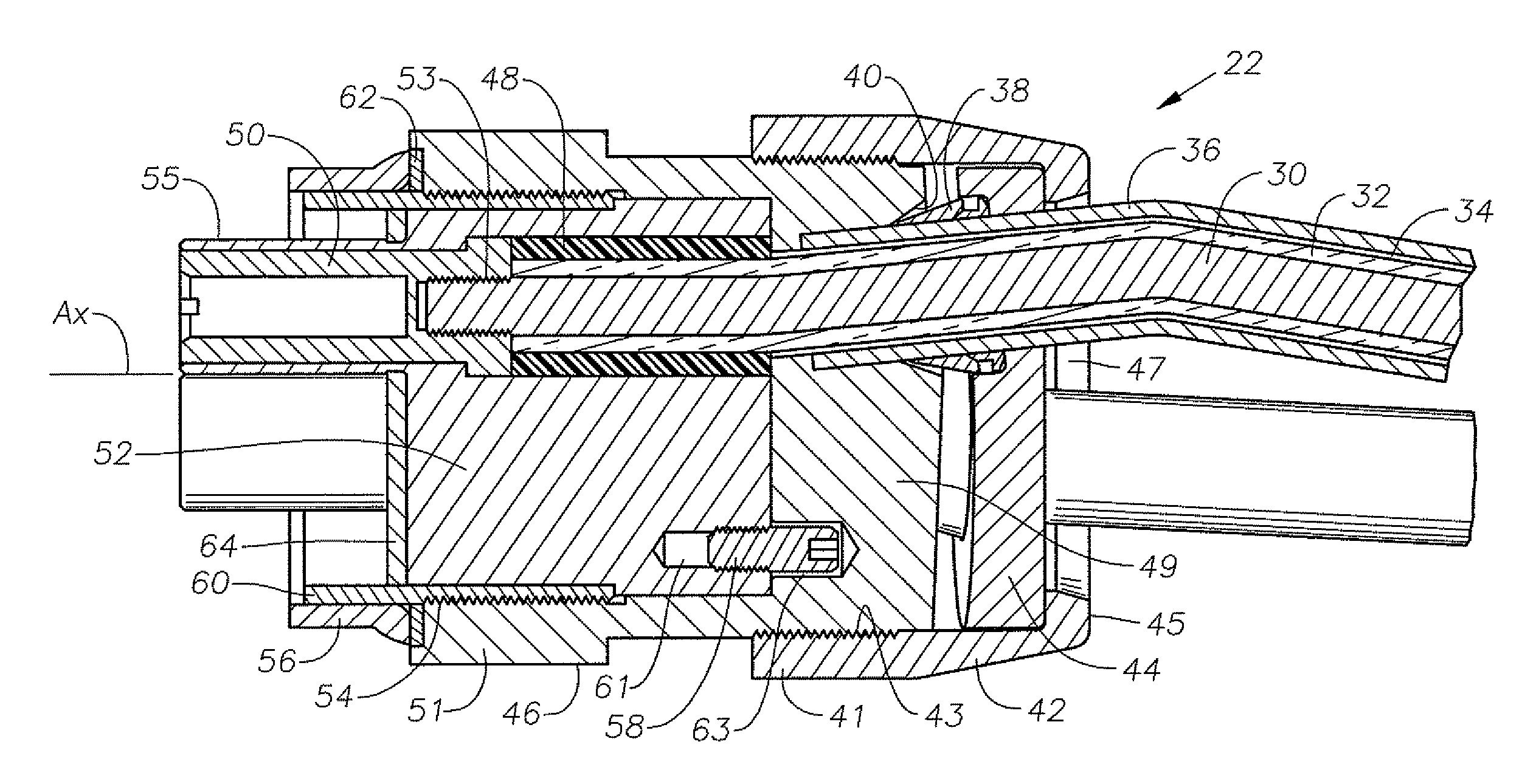
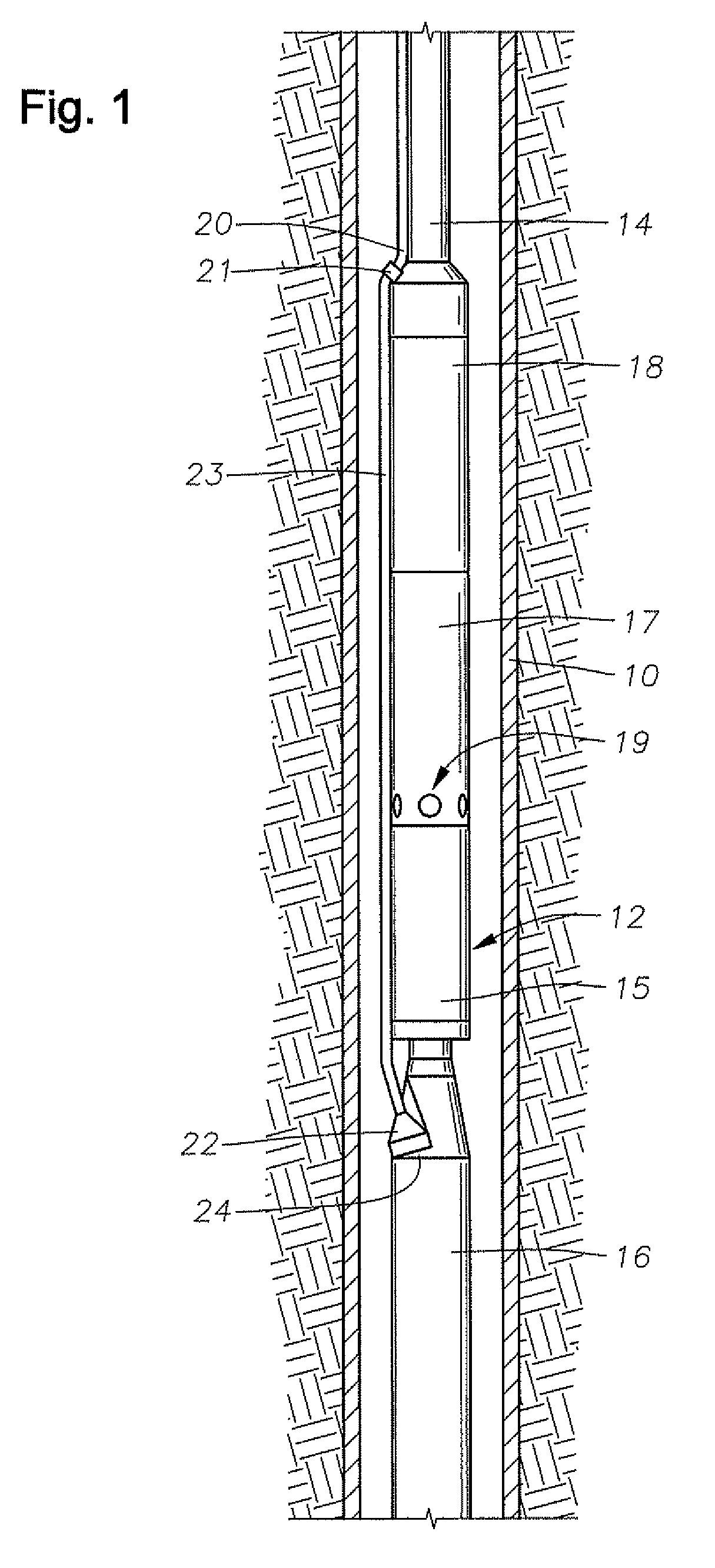
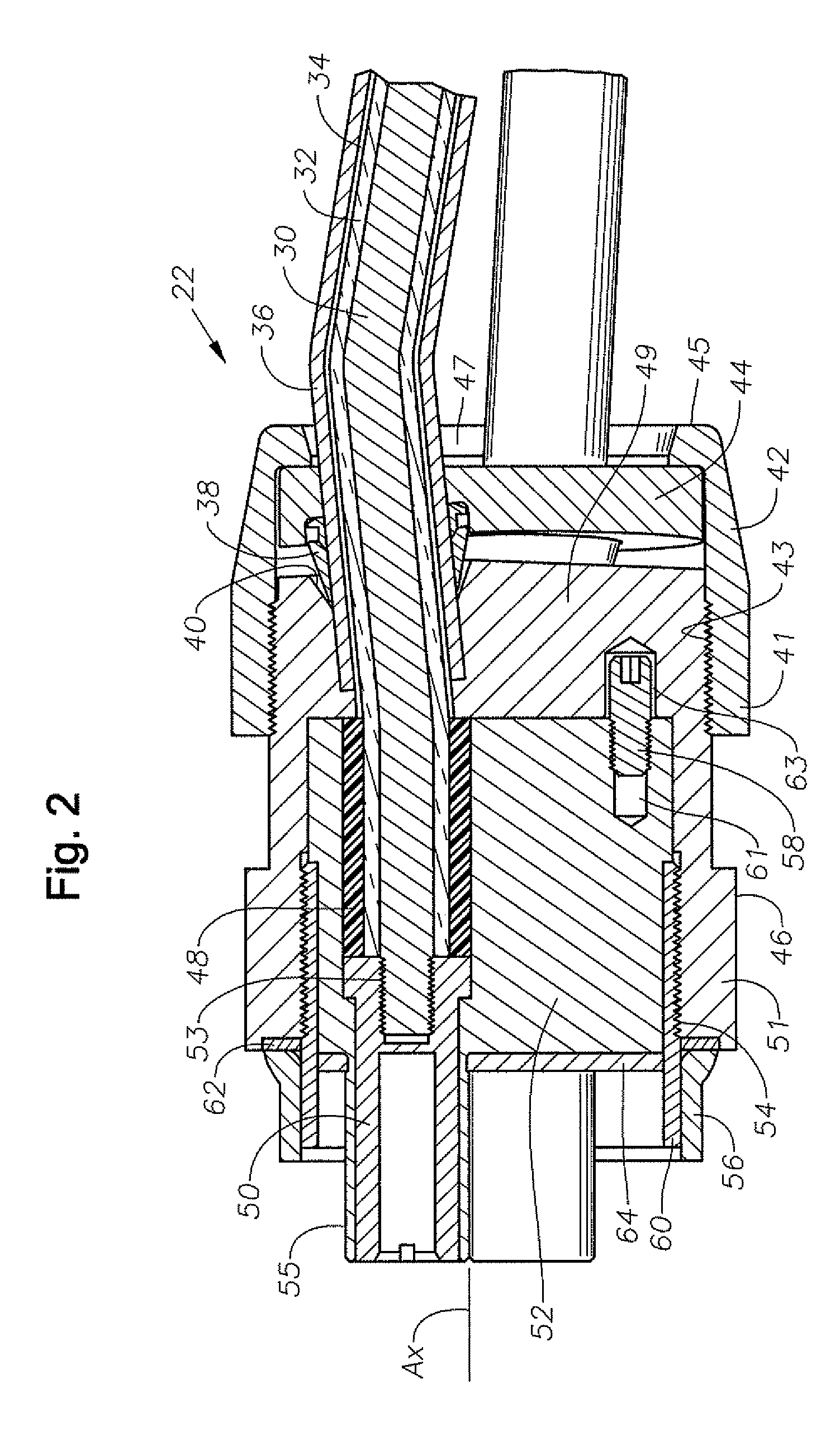
[0018]FIG. 1 is an elevational section view of well [10] having electrical submersible pumping system (ESP) [12] disposed therein. ESP [12] includes an electric motor [16], a seal / equalizer section [15], an optional separator [17], and a pump [18]. Pump [18] may comprise a centrifugal pump or a progressing cavity pump. Fluid inlets [19] are shown provided on separator [17] for providing a passage for receiving fluid into ESP [12]. Production tubing [14] is coupled to pump [18] discharge for conveying pressurized production fluid from the ESP [12] to surface. Cable [20] extends downhole, terminating in a connector [21] that electrically couples cable [20] to a motor lead [23]. Motor lead [23], on its lower terminal end, connects to a pothead connector [22] that electrically connects and secures motor lead [23] to motor housing [24] of electric motor [16]. In another embodiment, cable [20] can extend all the way from the surface to pothead connector [22], thereby eliminating the need ...


PUM

PropertyMeasurementUnit
non-conductiveaaaaaaaaaa
torqueaaaaaaaaaa
forceaaaaaaaaaa

Abstract

A pothead assembly for use under severe operating conditions. The pothead assembly includes a plurality of ferrules, a compression plate, a pothead housing, and a threaded collar. When the collar and a base portion of a pothead housing are engaged, the pothead assembly is operable to form a metal to metal seal on metal tubing that surrounds insulated wiring without the use of a solder joint or weld joint. The resulting pothead assembly has a lower profile than conventional potheads, does not require the use of tube connectors and is operable to form the seal in close proximity to the motor.

Description

RELATED APPLICATIONS[0001]This patent application claims priority to U.S. Provisional Patent Application Ser. No. 61 / 047,469 filed on Apr. 24, 2008, which is incorporated by reference in its entirety.FIELD OF THE INVENTION[0002]This invention relates in general to a subterranean connector for use in a wellbore. More particularly, the present invention is directed to a high temperature pothead connector used to provide power to a submersible motor. Yet more particularly, the present invention provides a pothead connector that is capable of withstanding extreme conditions, such as high temperatures and pressures, as well as highly corrosive environments.BACKGROUND[0003]A common type of electrical submersible pump comprises a centrifugal pump suspended on a string of tubing within a casing of the well. The pump is driven by a downhole electrical motor, normally a three-phase AC type. A power line extends from a power source at the surface alongside the tubing to the motor to supply pow...

Claims


Application Information

Patent Timeline
Patent Type & Authority Patents(United States)
IPC IPC(8): H01R13/52
CPCH01R13/523H01R13/533Y10T29/53209
Inventor FREY, JEFFREY GGLASSCOCK, TERRY LEDDINGS, FRANK WARREN
Owner BAKER HUGHES INC
Why Eureka
Try Eureka