Stub sill assemblies

a technology of stub sills and assemblies, which is applied in the direction of tank wagons, railway components, underframes, etc., can solve the problems of affecting the operation of the stub sill

Active Publication Date: 2022-04-28
GUNDERSON
View PDF5 Cites 0 Cited by
  • Summary
  • Abstract
  • Description
  • Claims
  • Application Information

AI Technical Summary

Benefits of technology

[0006]In one embodiment, the stub center sill includes a center sill having a generally horizontal top member, a pair of sill web side plates, and a bottom cover plate. The sill web side plates, where the bottom cover plate terminates, having a shape that includes or approximates one or more radiuses of curvature.
[0007]In one embodiment, the shape is approximated by four or more linear or planar segments.
[0008]In one embodiment, the shape includes a single radius of curvature or two or more radiuses of curvature.

Problems solved by technology

However, the above stub sills are generally heavy, costly, and do not effectively distribute loads into the cradle pad.

Method used


Image

  • Stub sill assemblies
  • Stub sill assemblies
  • Stub sill assemblies

Examples


Embodiment Construction

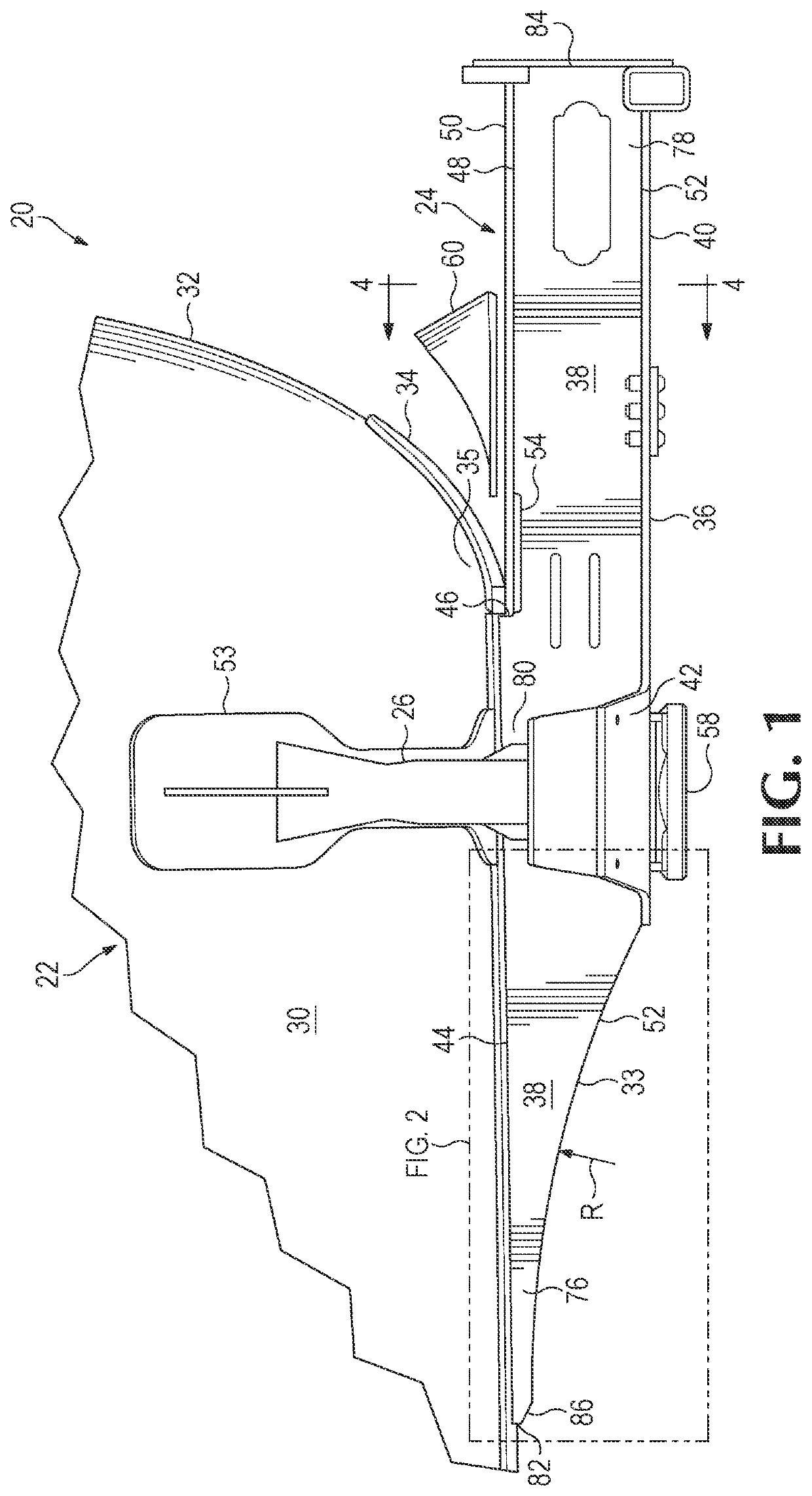
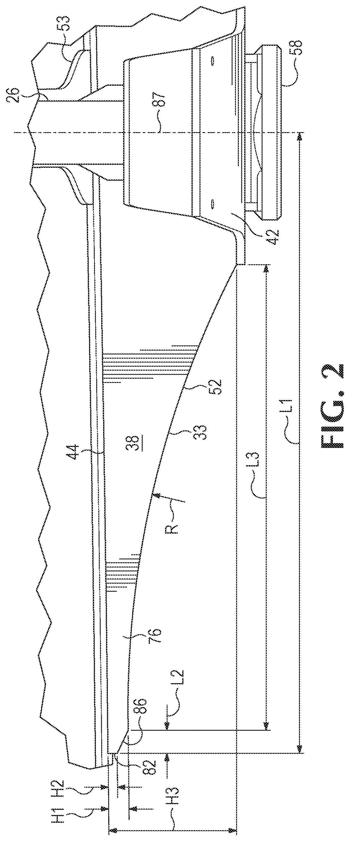
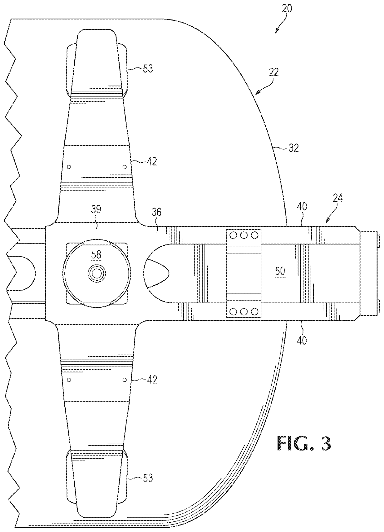
[0021]Referring now to the drawings which form a part of the disclosure herein, a portion of a railroad tank car 20 includes a tank 22 of steel or other suitable metal and intended for carrying liquid cargo, supported by a stub center sill 24 to which a tank saddle 26 is attached is shown in FIGS. 1-2. Conventionally, the saddle 26 extends from the base of a bottom cover (further discussed below) and around a generally cylindrical part 30 of the tank 22 a short distance longitudinally inboard from the convex head 32 of the tank 22. The stub center sill 24 may extend for distance inboard beyond the base of the bottom cover and toward the center of the length of the car 20, which may be referred to as a stub center sill inboard extension 33. Additionally, stub center sill 24 extends longitudinally outboard to receive a coupler (not shown). As shown, a doubler plate or head pad 34 of steel is present on a portion of the bottom of the tank above the stub center sill 24, extending around...


PUM


Abstract

Subassemblies for railroad tank cars are herein disclosed. In some embodiments, the subassembly includes a center sill including a generally horizontal top member and a pair of upright side plates spaced apart laterally from each other and a head brace having a lower margin welded to the top member of the center sill and an upper margin welded to the head of the tank. Each of the side plates having a top surface and an opposed bottom surface, the top surface being planar within a longitudinal central portion and at least a substantial part of a first longitudinal end portion. The bottom surface is planar and parallel to the top surface within the longitudinal central portion and a second longitudinal end portion. At least a substantial part of the bottom surface within the first longitudinal end portion has a shape that includes or approximates one or more radiuses of curvature.

Description

BACKGROUND OF THE INVENTION[0001]The present disclosure relates to railroad tank cars and in particular relates to stub sills attached to the ends of the tank of such a car.[0002]Railway tank cars may be used for carrying a variety of liquid, gaseous, and semi-liquid ladings. Such railway tank cars often include a horizontal, generally cylindrical tank. For many such tank cars, the tank not only carries the lading, but is also used as a primary structural member to carry longitudinal train loads.[0003]These cars typically have stub center sills on each end of the car along with transverse bolster assemblies. The sills carry couplers at their outer ends, and the bolsters have truck assemblies pivotally connected thereto to support the ends of the tank car on the railway tracks. Saddle assemblies, combined with the bolster assemblies, are typically provided at each end of the car. The saddle assembly usually is mated with a doubler plate or saddle pad that is attached to the tank. The...

Claims


Application Information

Patent Timeline
Patent Type & Authority Applications(United States)
IPC IPC(8): B61F1/14B61D5/06B61F1/02
CPCB61F1/14B61F1/02B61D5/06
Inventor KAVURI, HARIHARANATHASHIE-WINNS, SPENCERCURTIS, MATHEWSAXTON, GREGORY J.
Owner GUNDERSON
Why Eureka
Try Eureka