
Crawler robot

a robot and crawler technology, applied in the field of crawlers, can solve the problems of increasing size, inability to operate, energy consumption and mobility,

Inactive Publication Date: 2010-09-14
NAT INST OF ADVANCED IND SCI & TECH
View PDF28 Cites 24 Cited by
  • Summary
  • Abstract
  • Description
  • Claims
  • Application Information

AI Technical Summary

Benefits of technology

The present invention provides a crawler robot that can easily climb over high obstacles using a center-of-gravity-displacement mechanism. The robot has a triangular crawler device and a subordinate crawler device connected by a link, which allows for a higher step to be climbed over. The link is a one-joint link, and the robot can travel with both the triangular and subordinate crawlers in contact with ground. The triangular crawler device and subordinate crawler device differ in weight, and the link rotates to displace the center of gravity of the robot. The robot can also be raised and placed on a step portion by the subordinate crawler device, and the subordinate crawler device applies pressure from the rear side to grip the surfaces of the triangular crawlers in contact with the ground. The robot can also travel through rotation of the triangular crawler device about the support shaft. The center-of-gravity-displacement mechanism allows for higher step climbing as compared with conventional techniques.

Problems solved by technology

While capable of traveling on an irregular ground or the like, such a related art caterpillar type crawler robot as mentioned above involves a complicated mechanism to climb over, for example, a high obstacle, resulting in an increase in size and a problem in terms of energy consumption and mobility.
Further, many crawler robots are of a structure vertically asymmetrical, so when turned upside down, they become incapable of operation.

Method used


Image

  • Crawler robot
  • Crawler robot
  • Crawler robot

Examples


embodiment 1

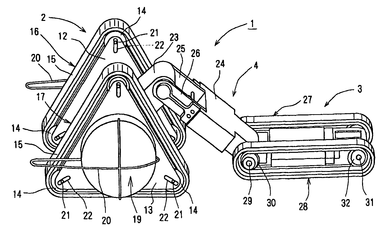
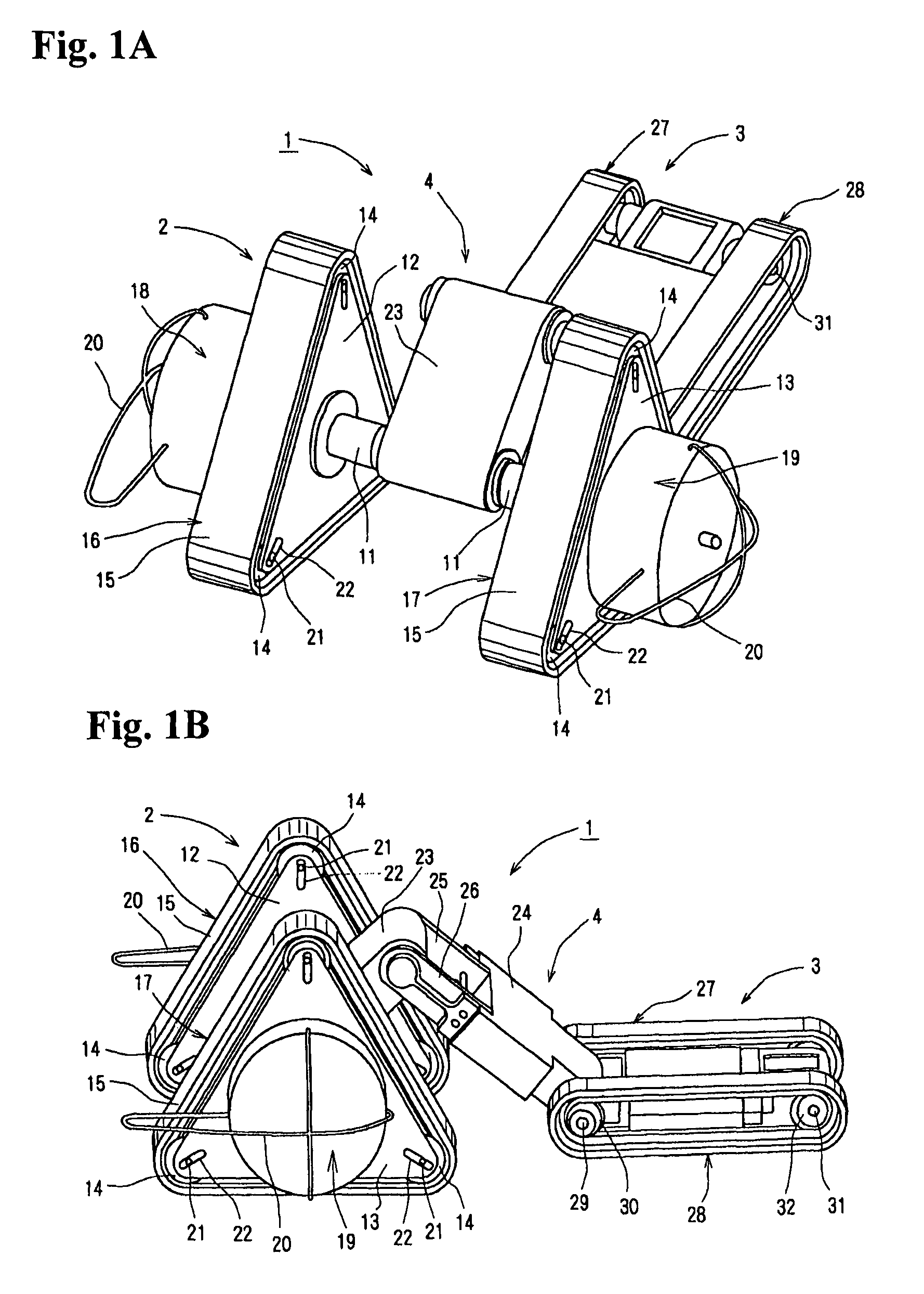
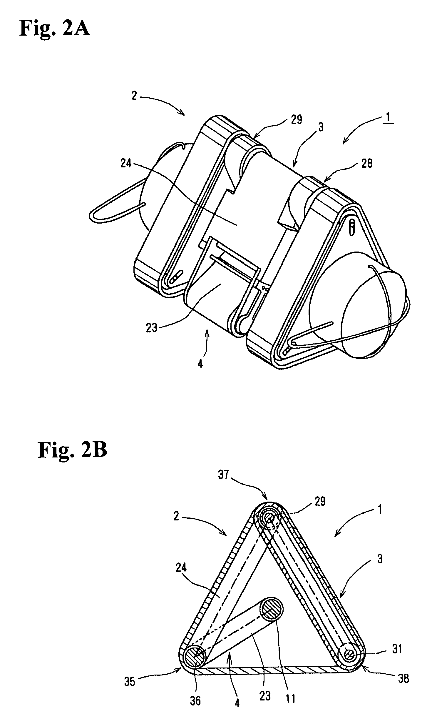
[0038]An embodiment of the present invention will be described with reference to the drawings. FIGS. 1A and 1B are perspective views showing one of various operational aspects of a crawler robot according to the exemplary embodiment, in which there is used a one-joint link composed of two links rotatably connected together. As described below, a crawler robot 1 is composed of a triangular crawler device 2 having triangular crawlers on both sides thereof, a subordinate crawler device 3 having standard type small crawlers on both sides thereof, and a one-joint link 4 connecting together the triangular crawler device 2 and the subordinate crawler device 3.

[0039]In the triangular crawler device 2, both ends of a central support shaft 11 are supported by frames, each of which is composed of an inner triangular frame 12 and an outer triangular frame 13, with rollers 14 being provided at the apex portions of the frames. Elastic crawlers 15 formed of an elastic material such as rubber and s...


PUM


Abstract

Disclosed is a crawler robot which, even of a small size, can climb over a high step and which can perform various aspects of operations. Rollers, are arranged at apexes of triangular frames, and elastic crawlers are wrapped around the rollers, with the two frames being connected by a central support shaft. Rotatably provided to the central support shaft is a one-joint link composed of a first link and a second link connected together by a rotation shaft. An end portion of the second link is rotatably connected with a front shaft of a subordinate crawler device equipped with crawlers wrapped around rollers. As a result, the crawler robot is composed of a triangular crawler device and the subordinate crawler device connected together by the one-joint link. The crawler robot can be operated by rotating and bending the link and by rotating the crawler devices in arbitrary directions.

Description

BACKGROUND OF THE INVENTION[0001]1. Technical Field[0002]Aspects of the present invention relate to a robot using crawlers as moving devices, and more particularly to a crawler robot having, on both sides of a robot main body, crawlers driven in a triangular form to thereby form a triangular crawler device, and further, including a small subordinate crawler device rotatably connected with the triangular crawler device by a link.[0003]2. Related Art[0004]Examples of the related art robots include stationary robots mainly installed in the production lines of plants, and movable robots equipped with moving devices of various types; the related art movable robots mainly adopt either a caterpillar type or a leg type moving system.[0005]Generally speaking, vehicles travel by using tires as in the case of automobiles, or by using caterpillars formed of iron or rubber belts as in the case of tanks. The belts used in the latter type of traveling system are called crawlers (or crawler belts)....

Claims


Application Information

Patent Timeline
Patent Type & Authority Patents(United States)
IPC IPC(8): B62D55/00
CPCB62D55/0655B62D55/075B62D55/18B62D55/30B62D59/04
Inventor KAMIMURA, AKIYA
Owner NAT INST OF ADVANCED IND SCI & TECH
Learn More