Connector for electrical wire-carrying conduits

Inactive Publication Date: 2010-09-14
ATKORE STEEL COMPONENTS INC
View PDF16 Cites 22 Cited by
  • Summary
  • Abstract
  • Description
  • Claims
  • Application Information

AI Technical Summary

Benefits of technology

[0008]The present invention provides a coupling device for electrical wire-carrying conduits, which allows easy assembly with overhead supporting members. The coupling device comprises a tubular member having opposed axially aligned ends which, according to one embodiment of the invention, is threaded at both ends for engagement with an externally threaded conduit. A pair of aligned stop members projecting from the middle of the inner surface of tubular member fix the position of each conduit and assure t

Problems solved by technology

While the conduit connector described in the aforementioned patent is designed to overcome the shortcomings of the

Method used


Image

  • Connector for electrical wire-carrying conduits
  • Connector for electrical wire-carrying conduits
  • Connector for electrical wire-carrying conduits

Examples


Example

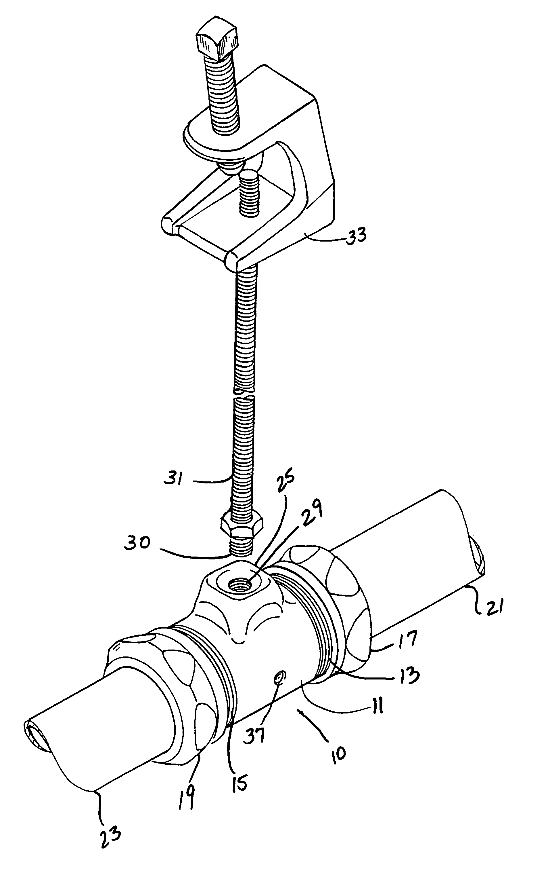
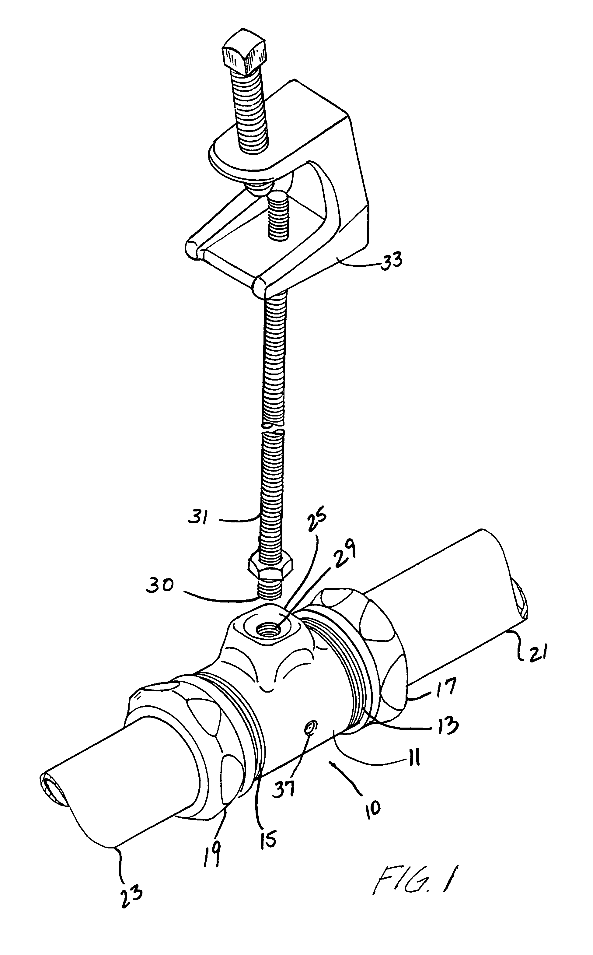
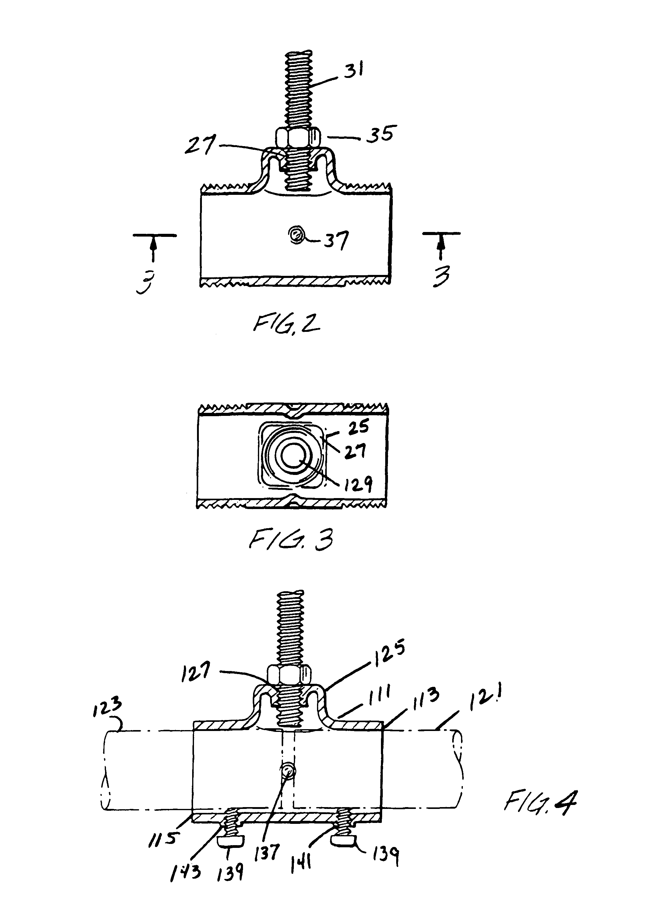
[0015]Referring to the embodiment of the invention illustrated in FIGS. 1-3, there is shown a coupling device or connector generally designated as 10 comprising a tubular connector or coupling device 11 having externally threaded ends 13 and 15, and a pair of coaxial internally threaded compression lock nuts 17 and 19 adapted to be threadedly engaged onto the respective threaded ends 13 and 15. Conduit or pipe sections 21 and 23 are inserted through the respective lock nuts 17 and 19 and are coaxially aligned through the connector, and a pair of ring washers (not shown), one slipped on each end of the tubular connector 11 serve to securely lock each pipe section at each end of the connector 11. Each ring washer has a slightly larger inside diameter than the outside diameter of each pipe so as to encircle the pipe and, when it is inserted through the lock nut and into the connector, each washer serves to securely lock the respective pipe sections in place without slippage. It must be...


PUM


Abstract

A coupling device for electrical wire-carrying conduits for assembly with an overhead support member having a stem with a free threaded end. The coupling device includes an integral tubular member having axially opposed ends, each of which receives an end of a mating conduit, and the integral top surface on the tubular member has an aperture for engagement with the free end of the stem of the supporting member.

Description

FIELD OF THE INVENTION[0001]This invention relates generally to connectors for conduits such as pipes, tubes and the like, and is particularly related to an improved connector or coupling device for electrical wire-carrying conduits and for securing the connector to a wall or a ceiling.BACKGROUND OF THE INVENTION[0002]Conduit connectors or couplings are commonly used for coupling conduits such as pipes or ducts which carry electrical transmission wires or cables through the conduits. One such connector is disclosed in U.S. Pat. No. 5,165,735 issued to Nardi et al. on Nov. 24, 1992. This patent describes a conduit coupling device comprising a tubular casing having a radial bore. Housed in the casing is a conduit clamp assembly which includes a pair of interlocking arcuate clamps coaxial with the casing. One of the clamps is fixed in position in the casing while a screw engages the tapped bore and bears on the other clamp. An internally threaded projection extends radially from the ca...

Claims


Application Information

Patent Timeline
IPC IPC(8): F16L3/00
CPCF16L3/1211F16L3/1222F16L3/133
Inventor SHEMTOV, SAMI
Owner ATKORE STEEL COMPONENTS INC
Why Eureka
Try Eureka