Variable position gas trap

a gas trap and variable position technology, applied in the direction of instruments, separation processes, borehole/well accessories, etc., can solve the problems of special lubricants, high cost, and affecting the operation of the gas trap, and affect the separation efficiency of gas bubbles from drilling fluid,

Active Publication Date: 2010-09-14
SCHLUMBERGER TECH CORP
View PDF26 Cites 19 Cited by
  • Summary
  • Abstract
  • Description
  • Claims
  • Application Information

AI Technical Summary

Problems solved by technology

The drilling fluid may contain other additives, such as special lubricants, and is relatively expensive.
If the drilling mud level in the tank or container changes the operation of the gas trap may be affected.
If the level of drilling fluid is too high, it may affect the efficiency of separation of the gas bubbles from the drilling fluid or, in an extreme case, mud may enter the analysis equipment.

Method used


Image

  • Variable position gas trap
  • Variable position gas trap
  • Variable position gas trap

Examples


Embodiment Construction

[0034]The embodiments discussed herein are merely illustrative of specific manners in which to make and use the invention and are not to be interpreted as limiting the scope of the instant invention.

[0035]While the invention has been described with a certain degree of particularity, it is to be noted that many modifications may be made in the details of the invention's construction and the arrangement of its components without departing from the spirit and scope of this disclosure. It is understood that the invention is not limited to the embodiments set forth herein for purposes of exemplification.

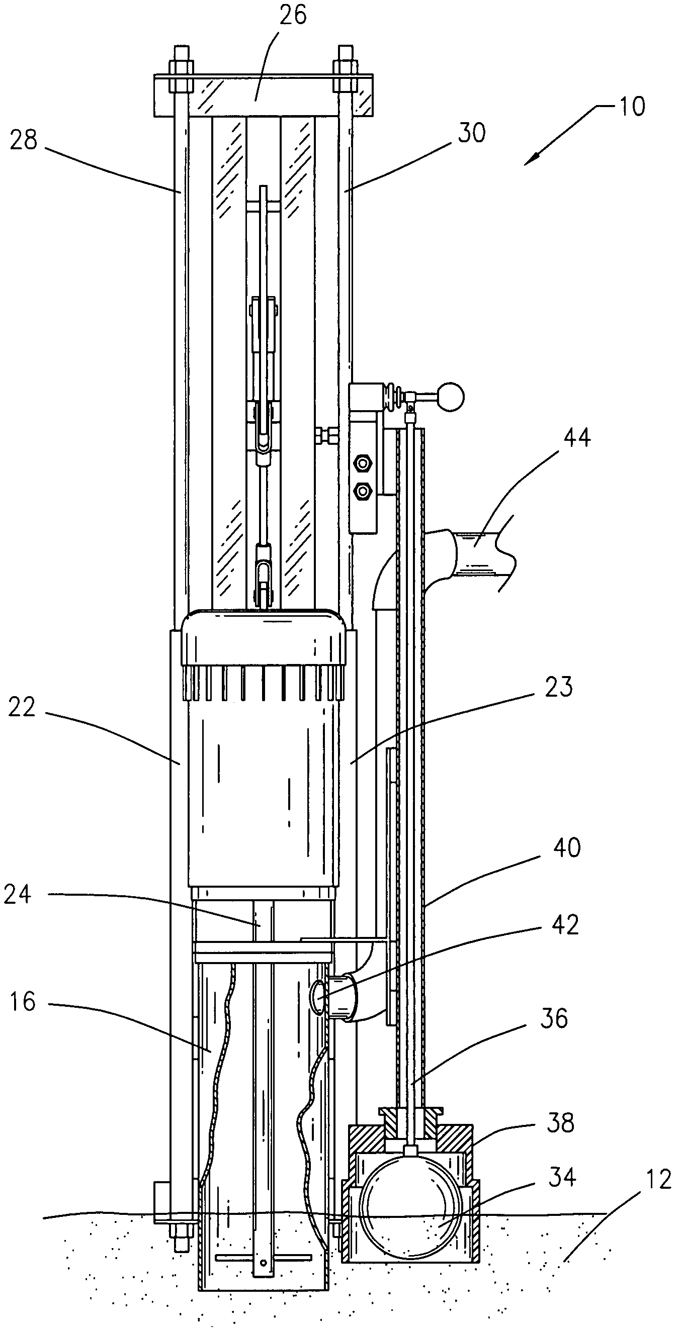
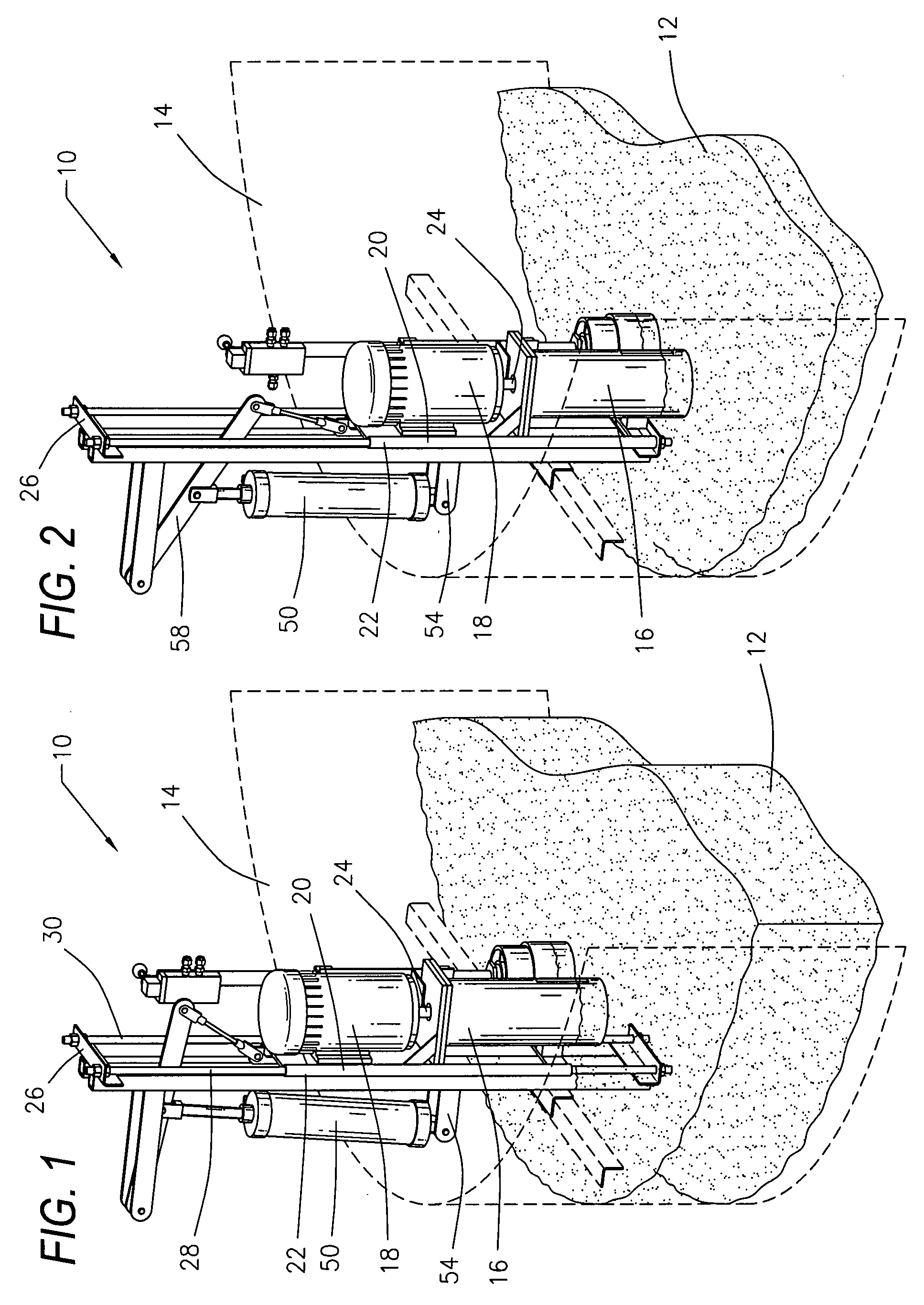
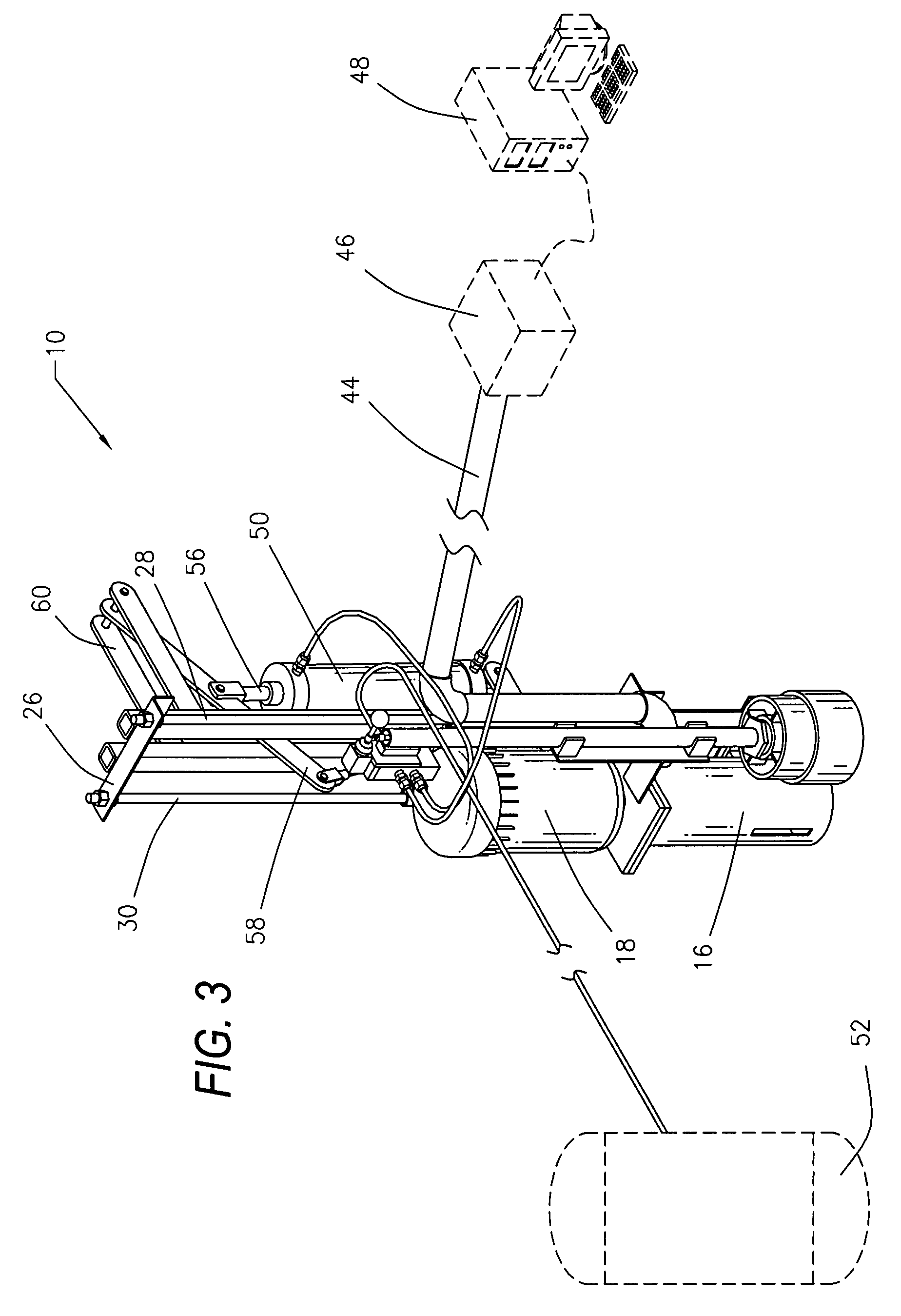
[0036]Referring to the drawings in detail, FIGS. 1 and 2 illustrate perspective views of a variable position gas trap apparatus 10 utilized to separate gases entrained in drilling fluid 12 in a container or tank 14 (shown by dash lines) wherein the level of the drilling fluid 12 in the tank 14 varies. Various hoses which are a part of the apparatus are not shown in FIGS. 1 and 2 for clari...


PUM

PropertyMeasurementUnit
inner diameteraaaaaaaaaa
outer diameteraaaaaaaaaa
heightaaaaaaaaaa

Abstract

A variable position gas trap apparatus and method to separate gases entrained in drilling fluid in a tank. The apparatus includes a gas trap attached to a carriage and a frame attached to the tank. A lever moveable by the float rod, activates the control valve to raise or lower the carriage having the gas trap container attached thereto. A feedback control loop is responsive to changes in the level of the drilling fluid in the tank. A mechanism is provided to mechanically and automatically move the carriage with respect to the frame in response to the feedback control loop.

Description

BACKGROUND OF THE INVENTION[0001]1. Field of the Invention[0002]The present invention is directed to a variable position gas trap apparatus and method used to separate gases entrained in drilling fluid in a tank. In particular, the present invention is directed to a variable position gas trap apparatus wherein a feedback control loop mechanically and automatically adjusts the height of the gas trap in response to changes in the level of the drilling fluid in the tank.[0003]2. Prior Art[0004]The use of drilling fluid or fluids while drilling subterranean wells is well-known. The drilling fluid or fluids may be aqueous-based, but are most often hydrocarbon or petroleum-based. The drilling fluids are referred to as base fluid, drilling mud or, simply, mud. Drilling fluid is used for a number of reasons. The drilling fluid is pumped downhole to the site where the drill bit is operating and is used to carry dirt, debris, rocks and chips broken off by action of the drill bit. The drilling...

Claims


Application Information

Patent Timeline
Patent Type & Authority Patents(United States)
IPC IPC(8): B01D19/00
CPCE21B21/067E21B49/005
Inventor STERNER, STEVEN MICHAEL
Owner SCHLUMBERGER TECH CORP
Why Eureka
Try Eureka