Power supply mounting apparatus for lighting fixture

a technology for mounting apparatus and lighting fixtures, which is applied in the direction of lighting and heating apparatus, fixed installation, lighting support devices, etc., can solve the problems of difficult positioning of led power units (led drivers) for lighting fixtures using led arrays, difficult positioning of such components, and difficult development of fixtures, so as to reduce the development and manufacturing costs of lighting fixtures, and easy and secure mounting of power supply units. , the effect of reducing the need for electronic led drivers

Active Publication Date: 2010-09-21
IDEAL IND LIGHTING LLC
View PDF9 Cites 16 Cited by
  • Summary
  • Abstract
  • Description
  • Claims
  • Application Information

AI Technical Summary

Benefits of technology

[0009]Another object of the invention is to provide an improved lighting fixture that provides for easy and secure mounting of a power supply unit.
[0051]The improved LED floodlight fixture of this invention overcomes the problems discussed above. Among other things, the invention provides substantially water / air-tight enclosure of electronic LED drivers inside the fixture, while still accommodating heat-dissipation requirements. And, the fixture of this invention is both adaptable for varying applications and mountings, and relatively inexpensive to manufacture.

Problems solved by technology

Floodlights using LED modules as light source for various applications present particularly challenging problems in fixture development, particularly when floodlight mounting locations and structures will vary.
Among other things, placement of the electronic LED power units (LED drivers) for lighting fixtures using LED arrays can be particularly problematic.
In some cases, keeping such electronic LED drivers in a water / air-tight location may not be difficult, but if mounting locations and structures vary, then location and protection of such components becomes difficult and adds development costs and potential problems.
Heat dissipation is another problem for LED floodlights.
And, the goals of dealing with heat dissipation and protection of electronic LED drivers can often be conflicting, contrary goals.

Method used


Image

  • Power supply mounting apparatus for lighting fixture
  • Power supply mounting apparatus for lighting fixture
  • Power supply mounting apparatus for lighting fixture

Examples


Embodiment Construction

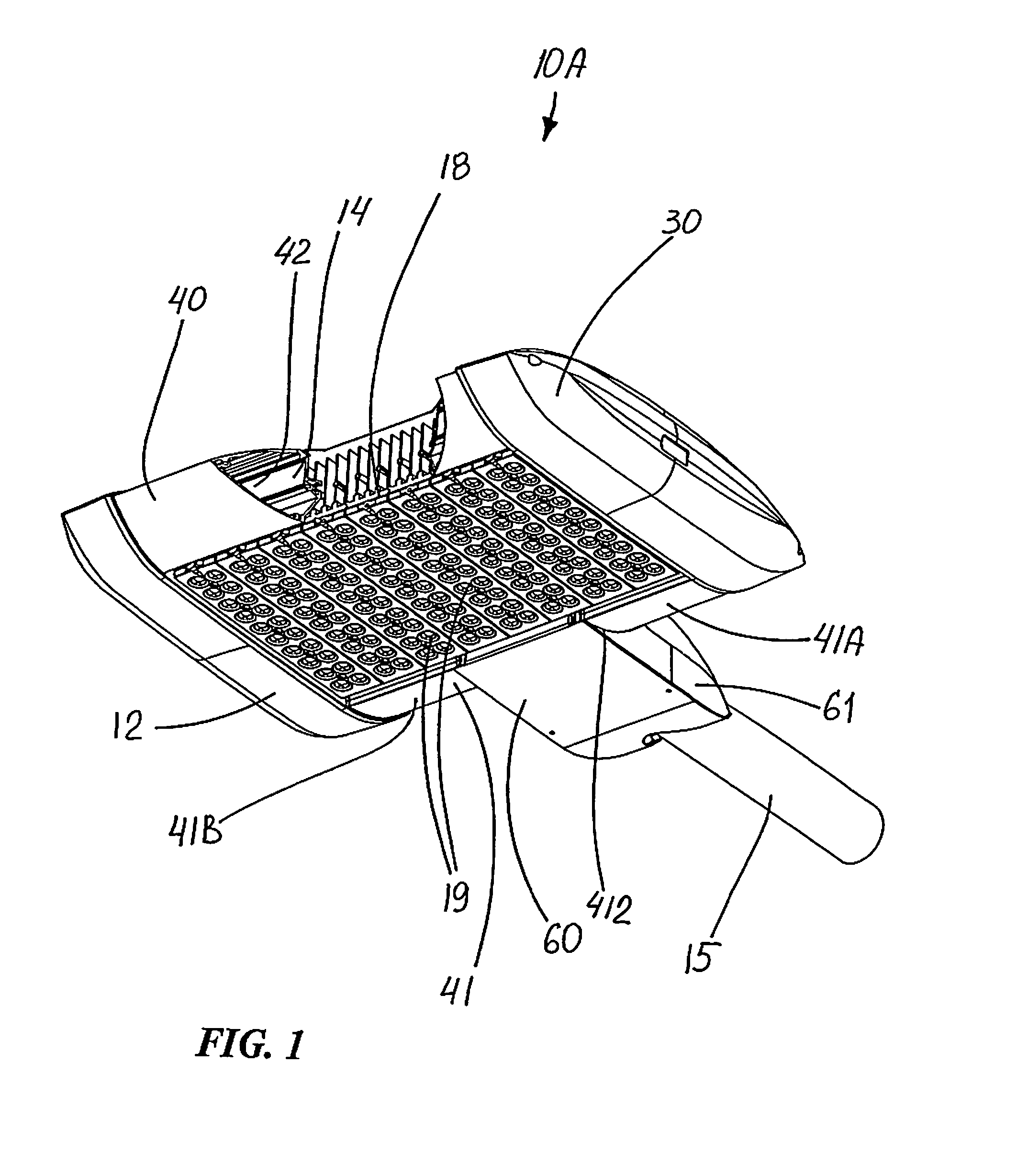
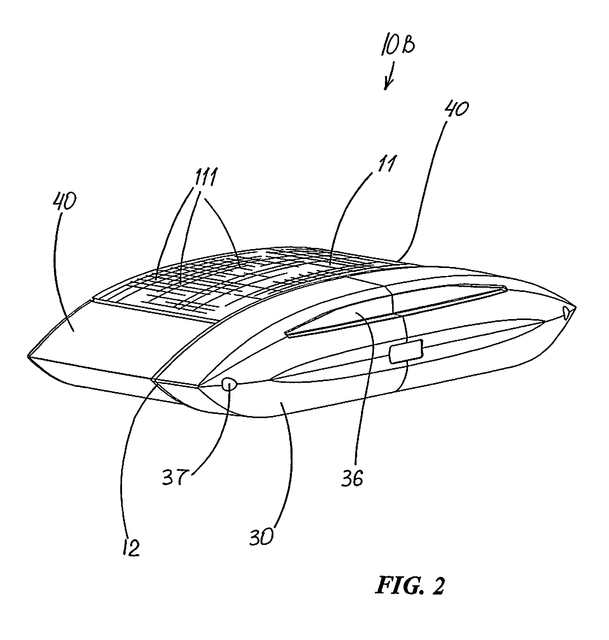
[0072]FIGS. 1-15 illustrate an LED floodlight fixtures 10A-10D. Common or similar parts are given the same numbers in the drawings of both embodiments, and the floodlight fixtures are often referred to by the numeral 10, without the lettering used in the drawings, and in the singular for convenience.

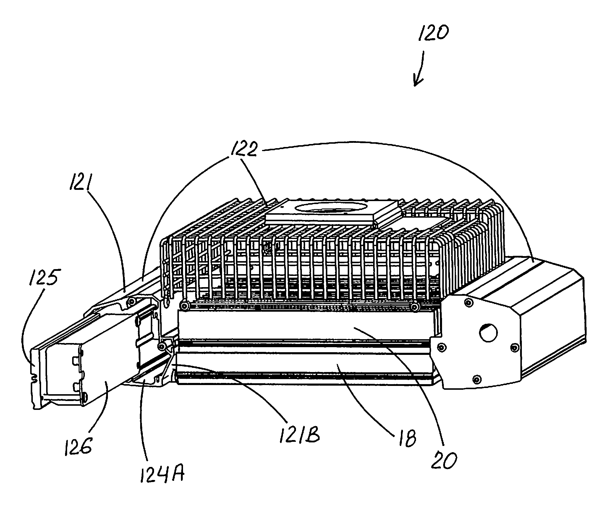
[0073]Floodlight fixture 10 includes a housing 12 that forms a substantially water / air-tight chamber 14, at least one electronic LED driver 16 which is enclosed within chamber 14, and an LED assembly 18 that is secured with respect to housing 12 adjacent thereto in non-water / air-tight condition. LED assembly 18 has a plurality of LED-array modules 19 each secured to an LED heat sink 20.

[0074]As seen in FIGS. 1-4, 7 and 8, housing 12 includes a frame structure 30 forming a frame-portion 32 of chamber 14 with an opening edge 34 thereabout and a border structure 40 (sometimes referred to as a nose structure 40) secured to frame structure 30 and forming a border-portion 42 (sometimes referre...


PUM


Abstract

A lighting fixture including a housing having a chamber defined by a surrounding wall, at least one power-supply unit within the chamber, and a slidable interlock securing the power-supply unit to the surrounding wall. The interlock includes a linear groove on one of the power-supply unit and the wall, and a mating projection on the other of the power-supply unit and the wall and slidably receivable into the groove. The power-supply unit is readily securable within the chamber by slidable engagement with the surrounding wall. It is preferred that the power-supply unit be secured closely against the fixture-exterior wall-portion, thus facilitating heat transfer from the power-supply unit to outside the fixture.

Description

RELATED APPLICATIONS[0001]This application is a continuation-in-part of currently pending U.S. application Ser. No. 11 / 864,300, filed on Sep. 28, 2007, the contents of which are incorporated herein by reference.FIELD OF THE INVENTION[0002]This invention relates to lighting fixtures and, more particularly, to power supply mounting within lighting fixtures using LED modules.BACKGROUND OF THE INVENTION[0003]In recent years, the use of light-emitting diodes (LEDs) for various common lighting purposes has increased, and this trend has accelerated as advances have been made in LEDs and in LED arrays, often referred to as “LED modules.” Indeed, lighting applications which previously had been served by fixtures using what are known as high-intensity discharge (HID) lamps are now beginning to be served by fixtures using LED-array-bearing modules. Such lighting applications include, among a good many others, roadway lighting, factory lighting, parking lot lighting, and commercial building lig...

Claims


Application Information

Patent Timeline
Patent Type & Authority Patents(United States)
IPC IPC(8): F21S4/00
CPCF21V15/01F21V23/026F21V29/004F21V31/03F21V29/76F21V29/75F21S8/086F21W2131/103F21Y2101/02F21V29/74F21Y2115/10
Inventor KINNUNE, BRIAN
Owner IDEAL IND LIGHTING LLC
Why Eureka
Try Eureka