Pressure distribution detector utilizing electromagnetic coupling

a detector and electromagnetic coupling technology, applied in the direction of fluid pressure measurement using inductance variation, instruments, force/torque/work measurement, etc., can solve the problems of difficult to realize a sheet-like pressure measurement device, difficult to increase the size of the detection surface, and difficult to form the mechanism in a thin sheet-like shape. , to achieve the effect of wide application range and high noise toleran

Active Publication Date: 2010-09-21
NEWCOM
View PDF8 Cites 12 Cited by
  • Summary
  • Abstract
  • Description
  • Claims
  • Application Information

AI Technical Summary

Benefits of technology

[0035]The pressure distribution detector according to the present invention has the following advantages: the size of the detection surface thereof can be larger; high tolerance for noise; and capable of detecting pressure distribution without being influenced by the shape of a surface to be detected and installation condition. Further, the pressure distribution detector according to the present invention can be fitted to a surface of arbitrary shape, so that the detector has a wide range of application.

Problems solved by technology

However, the core and the differential coil each have a certain degree of thickness, so that it is difficult to form the mechanism in a thin sheet-like shape.
Accordingly, it is difficult to realize a sheet-like pressure measurement device by utilizing the above system.
These pressure distribution detectors have comparatively high impedance, so that they are susceptible to noise, and, therefore, it is difficult to increase the size of the detection surface thereof.

Method used


Image

  • Pressure distribution detector utilizing electromagnetic coupling
  • Pressure distribution detector utilizing electromagnetic coupling
  • Pressure distribution detector utilizing electromagnetic coupling

Examples


first embodiment

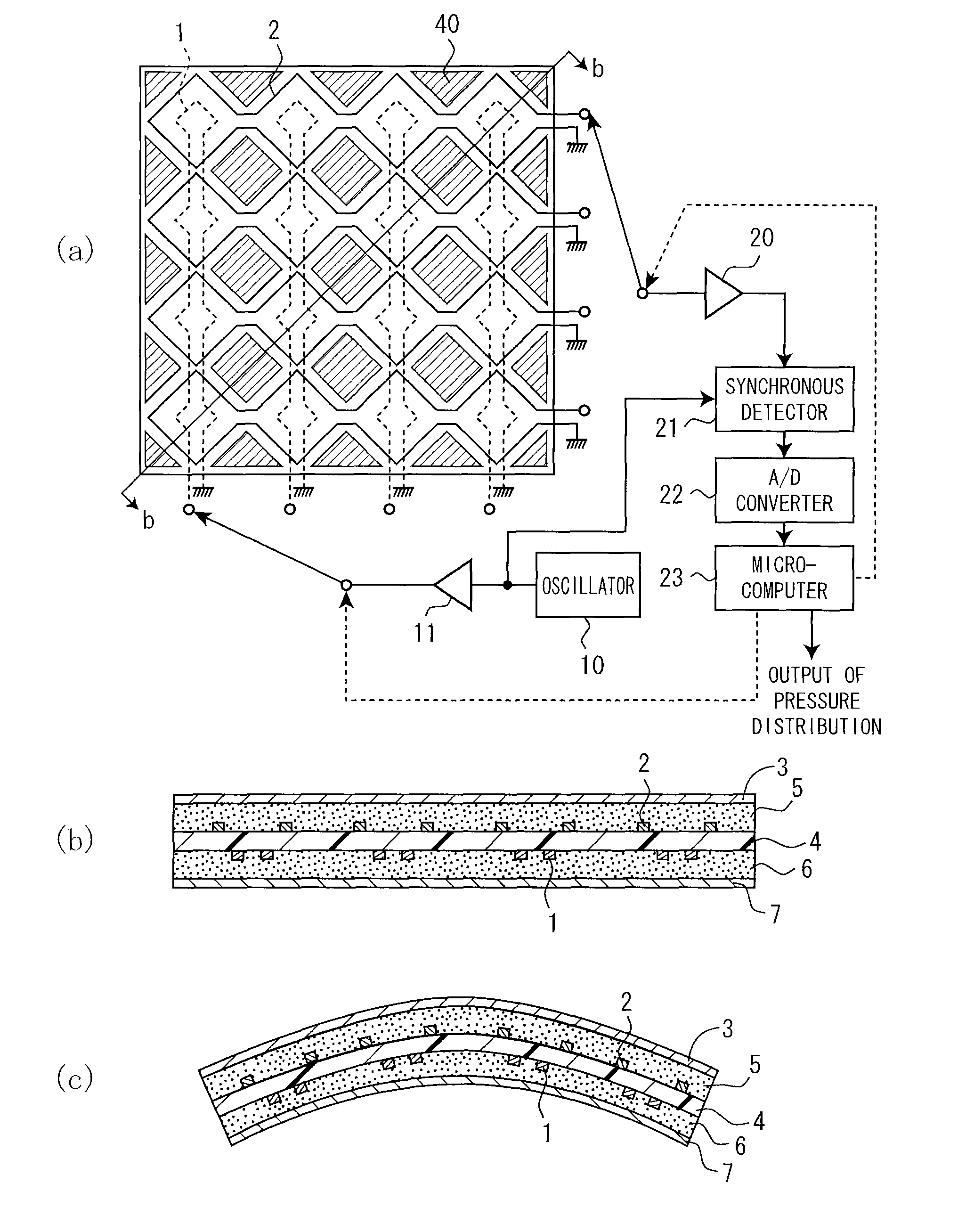
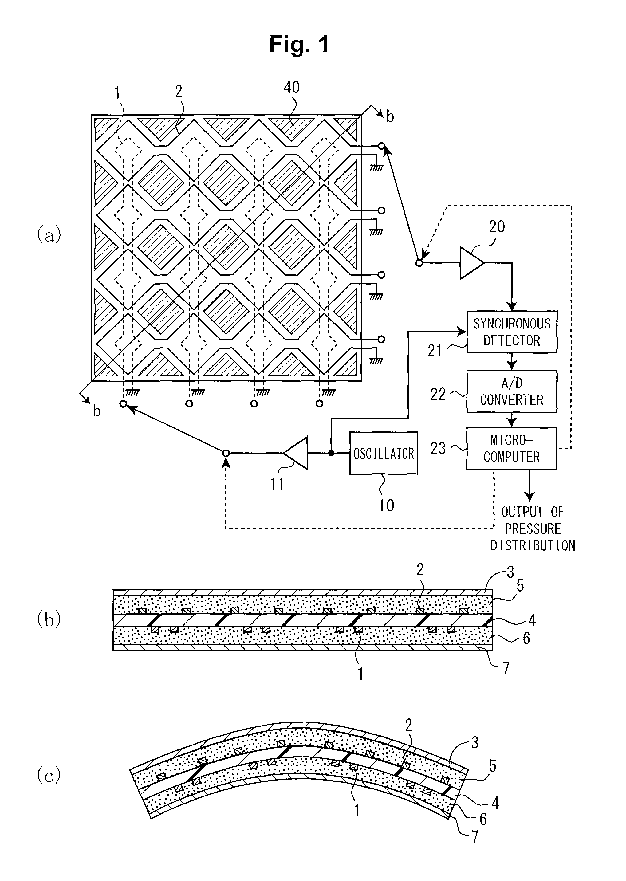
[0065]Now, preferred embodiments according to the present invention is explained with reference to the accompanying drawings. FIGS. 1(a) to 1(c) are views for explaining a pressure distribution detector according to the present invention. FIG. 1(a) is a partly transparent schematic plan view of the pressure distribution detector, FIG. 1(b) is a cross-sectional view thereof taken along b-b line, and FIG. 1(c) is a cross-sectional view thereof in a curved state. As shown in FIGS. 1(a) and 1(b), the pressure distribution detector of the present invention is mainly constituted by a plurality of drive coils 1, a plurality of detection coils 2, a variable electromagnetic coupling member 3 provided adjacent to the coils, a drive circuit connected to the drive coils 1, and a detection circuit connected to the detection coils 2.

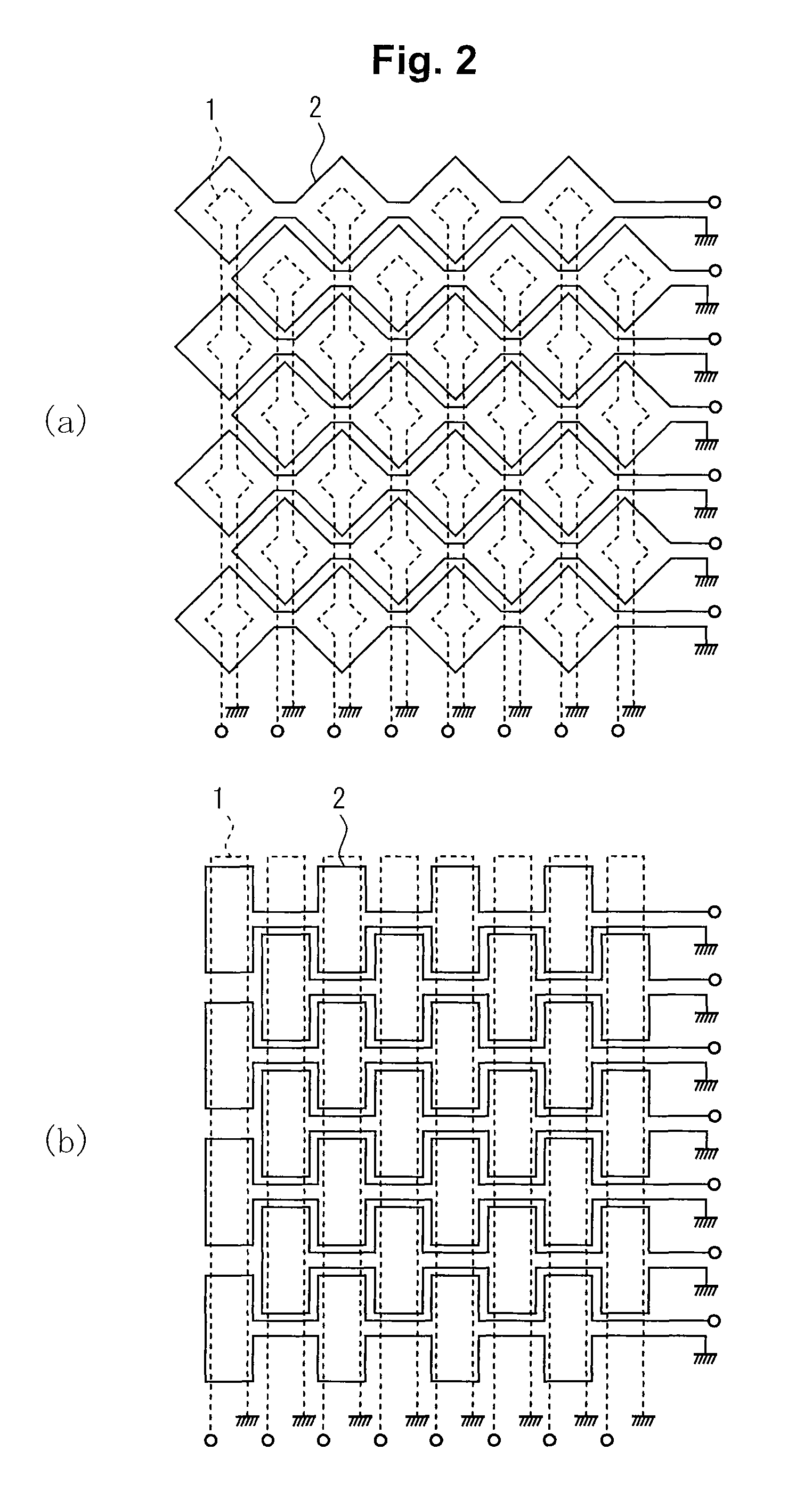
[0066]The plurality of drive coils 1 are serially connected to constitute a plurality of drive coil rows which are arranged in parallel to each other. The plurality o...

fourth embodiment

[0092]Further, in the case where the pressure distribution detector configured as the fourth embodiment is transport to an installation location, the device can be divided in units for transportation. Further, in the case where flexibility is provided with each unit, it can be transported in a rolled state.

[0093]Next, a pressure distribution detector according to a fifth embodiment of the present invention will be described. In the present embodiment, a reference coil is provided in addition to the drive coil and the detection coil so as to increase mainly signal-to-noise ratio. FIGS. 6(a) and 6(b) are views for explaining a pressure distribution detector according to a fifth embodiment of the present invention. FIG. 6(a) is a schematic explanatory view showing respective layers in a divided manner for easy understanding of the connection configuration of coils of each layer, and FIG. 6(b) is a cross-sectional view thereof. In FIGS. 6(a) and 6(b), the same reference numerals as thos...

fifth embodiment

[0096]As described above, in the fifth embodiment, the detection coil 2 and the reference coil 41 have substantially the same configuration, so that even if surrounding noise is superimposed on the induced voltage or induced current of the coil, it is superimposed on the detection coil 2 and the reference coil 41 in the same manner as each other. As a result, the surrounding noise to the detection coil 2 and the reference coil 41 are canceled in the differential amplifier 25. Accordingly, signal-to-noise ratio can be improved to enable high-sensitive measurement.

[0097]Although the drive coil and the detection coil is directly electromagnetically coupled to each other in the above embodiments, the pressure distribution detector according to the present invention is not limited to this configuration but may have a configuration in which the drive coil and the detection coil is electromagnetically coupled to each other in an indirect manner. In the following, a pressure distribution de...


PUM

PropertyMeasurementUnit
distanceaaaaaaaaaa
pressureaaaaaaaaaa
degree of electromagnetic couplingaaaaaaaaaa

Abstract

A pressure distribution detector is less influence by installation environment, that is, a pressure distribution detector that detection sensitivity or detection accuracy is less adversely affected even if the device is fitted not only to a flat surface but also a surface having an arbitrary shape such as a curved surface. The pressure distribution detector comprises a plurality of drive coils (1) provided on a substrate, a plurality of detection coils (2) electromagnetically coupled with the plurality of drive coils in pairs respectively, and a spacer (4) for keeping a constant distance between the plurality of drive coils and the plurality of detection coils, respectively. In order to vary the degree of electromagnetic coupling between the drive coil and the detection coil, a variable electromagnetic coupling (3) formed of a conductor or a magnetic body is provided movably adjacent to the drive coil and / or the detection coil. The drive coil is driven through a drive circuit and a change in the degree of electromagnetic coupling between the drive coil and the detection coil is detected by a detection circuit from the detection coil.

Description

CROSS REFERENCE TO RELATED APPLICATION[0001]This is a 35 U.S.C. §371 application of and claims priority to PCT International Application No. PCT / JP / 2006 / 324328, which was filed Dec. 6, 2006, and which claims priority to Japanese Patent Application No. 2006-231225, which was filed Aug. 28, 2006, and which claims priority to Japanese Patent Application No. 2006-011748, which was filed Jan. 19, 2006, and the teachings of all the applications are incorporated herein by reference.TECHNICAL FIELD[0002]The present invention relates to a pressure distribution detector utilizing electromagnetic coupling caused by coils and, more particularly to a pressure distribution detector that keeps a constant distance between a drive coil and a detection coil and is less influenced by the installation environment.BACKGROUND ART[0003]A pressure distribution detector has widely been used in various fields such as seat pressure detection of vehicles such as a car, welfare devices such as a bed, medical or...

Claims


Application Information

Patent Timeline
Patent Type & Authority Patents(United States)
IPC IPC(8): G01B7/24G01L1/12G01R33/18
CPCG01L1/14G01L9/00G01L9/10
Inventor OGAWA, YASUJI
Owner NEWCOM
Why Eureka
Try Eureka