Shot image display system, image receiving device, control method for image receiving device, and server

a display system and image technology, applied in the field of image display system, can solve the problems of large system structure, difficult to apply the related-art image blur preventing technique to portable devices such as videophones, and difficulty in clearly displaying small characters by videophones, etc., to achieve reduced processing load, less complicated structure, and reduced blur

Active Publication Date: 2010-09-21
138 EAST LCD ADVANCEMENTS LTD
View PDF11 Cites 49 Cited by
  • Summary
  • Abstract
  • Description
  • Claims
  • Application Information

AI Technical Summary

Benefits of technology

[0007]It is an advantage of some aspects of the invention to provide a shot image display system capable of reducing blurs of images on the image receiving side without complicating structure, an image receiving device, and a control method for the image receiving device, and a server.

Problems solved by technology

It is particularly difficult to clearly display small characters by videophone.
However, the system structure which uses the related-art image blur preventing technique is large-sized since a mechanism for physically shifting the projector and the screen or audience is required.
It is therefore difficult to apply this technique to portable devices such as a videophone.

Method used


Image

  • Shot image display system, image receiving device, control method for image receiving device, and server
  • Shot image display system, image receiving device, control method for image receiving device, and server
  • Shot image display system, image receiving device, control method for image receiving device, and server

Examples


application example

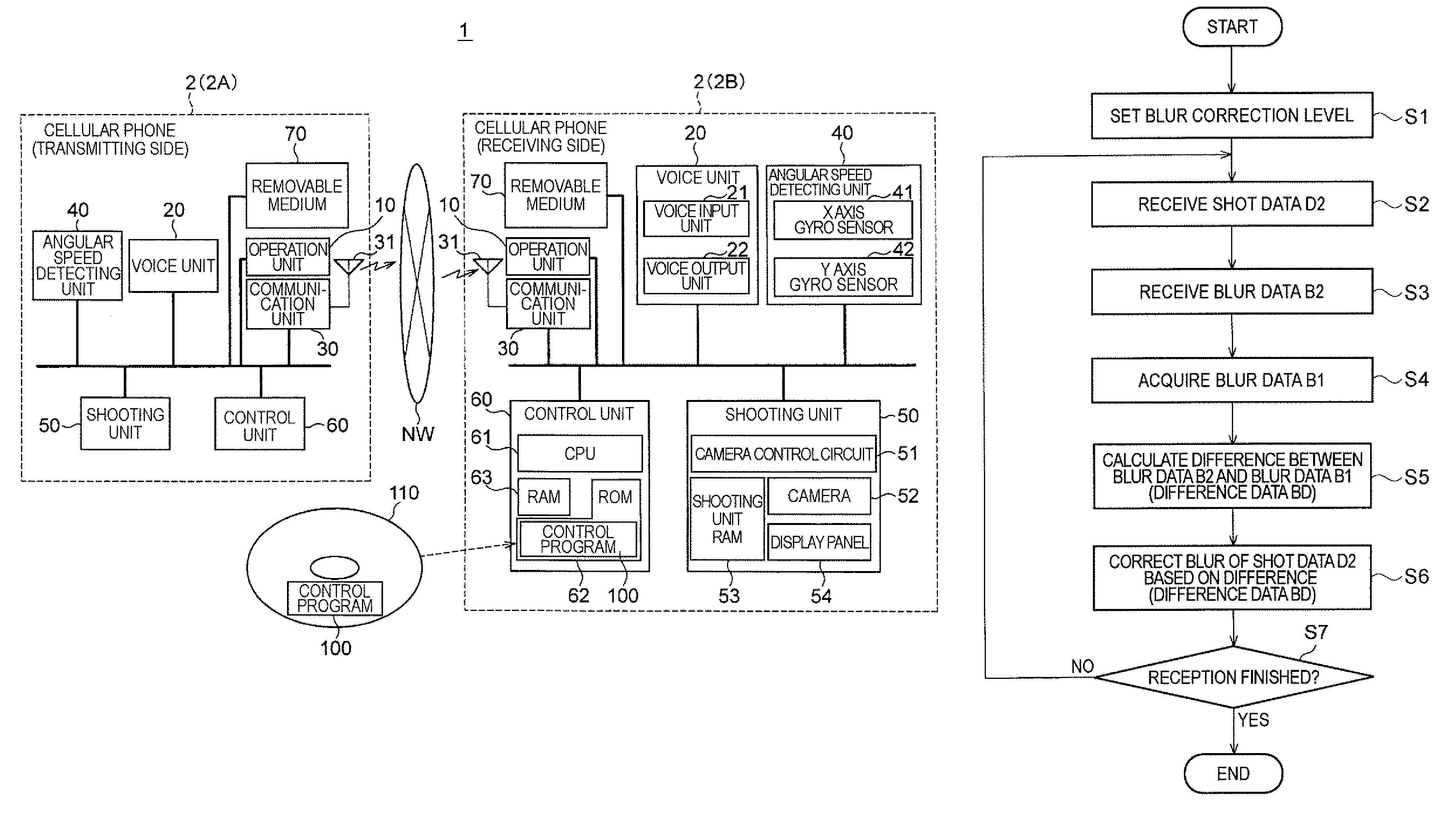
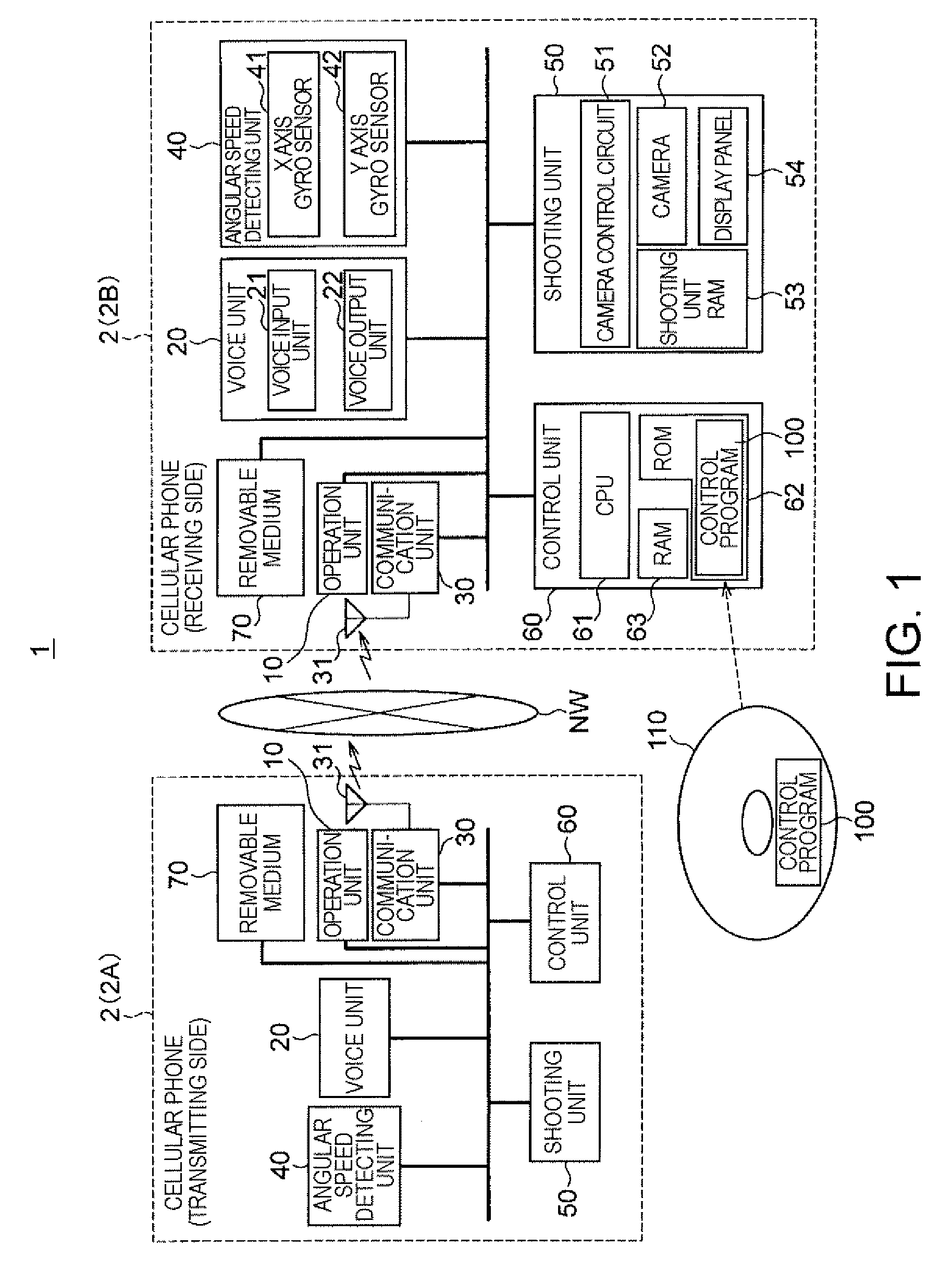
[0072]According to the embodiment discussed above, the receiving device 2B detects its own blurs and executes blur correction for shot images transmitted from the transmitting device 2A in communication based on the difference between the blur of the transmitting device 2A and the blur of the receiving device 25. However, blur correction may be performed for shot images from the transmitting device 2A in communication based on only the blur volume of the transmitting device 2A without detection of the blur volume of the receiving device 2B. In this case, the processing load on the receiving side can be reduced.

[0073]In the above embodiment, it is possible that the transmitting device 2A executes blur correction for images shot by the transmitting device 2A based on the blur detected by the transmitting device 2A and transmit the shot images after blur correction to the receiving device 2B. In this case, the receiving device 2B may perform blur correction correcting its own blur for ...


PUM


Abstract

A shot image display system includes a shooting device for transferring a shot image and blur produced at the time of shooting, and an image receiving device for receiving the shot image and blur transmitted from the shooting device. The image receiving device includes a blur correcting unit for executing blur correction for the received shot image based on the received blur, and a display unit for displaying the shot image corrected by the blur correcting unit.

Description

BACKGROUND[0001]1. Technical Field[0002]The present invention relates to a shot image display system which receives and displays shot images, an image receiving device, and a control method for the image receiving device, and a server.[0003]2. Related Art[0004]A cellular phone having a videophone function which provides an image of a person connected by phone as well as ordinary voice communication is known (for example, see JP-A-2002-27050). In case of videophone communication where the image shooting side and the image receiving side are discrete devices, blurred images are displayed on the image receiving side due to blurs caused on the shooting side or the receiving side. It is particularly difficult to clearly display small characters by videophone.[0005]According to a known image blur preventing technique used in a projector which projects images on a screen, blurs of the projector side and the screen or audience side are separately detected, and at least the position of eithe...

Claims


Application Information

Patent Timeline
Patent Type & Authority Patents(United States)
IPC IPC(8): G03B17/00G03B13/30G03B17/18H04N5/228
CPCG03B17/00
Inventor NAGAISHI, MICHIHIROSAKAMOTO, KAZUHIRO
Owner 138 EAST LCD ADVANCEMENTS LTD
Why Eureka
Try Eureka