Method and apparatus for a federation control plane in an orthogonal system

a control plane and orthogonal system technology, applied in the direction of instruments, electric digital data processing, etc., can solve the problems of cumbersome control plane architectures in some applications, affecting the quality of control planes,

Inactive Publication Date: 2010-09-21
GENERAL DYNAMICS ADVANCED INFORMATION SYST INC
View PDF28 Cites 13 Cited by
  • Summary
  • Abstract
  • Description
  • Claims
  • Application Information

AI Technical Summary

Problems solved by technology

While the unique interconnect approaches of orthogonal system architectures has yielded improvements in communication fabric construction over non-orthogonal system architectures, it has also imposed cumbersome control plane architectures in some applications.
As such, these approaches have led to cabling challenges and have required elaborate communications architectures to provide the control capability described above.
Further, these approaches can suffer from communication delays and synchronization errors, and from dropped or corrupted packets traversing the associated networking.

Method used


Image

  • Method and apparatus for a federation control plane in an orthogonal system
  • Method and apparatus for a federation control plane in an orthogonal system
  • Method and apparatus for a federation control plane in an orthogonal system

Examples


Embodiment Construction

[0016]As illustrated in the discussion below, various embodiments of the present invention are directed at aspects of an orthogonal system architecture. For illustration and explanation purposes, the same reference numbers will generally be used throughout the drawings to refer to the same or like parts.

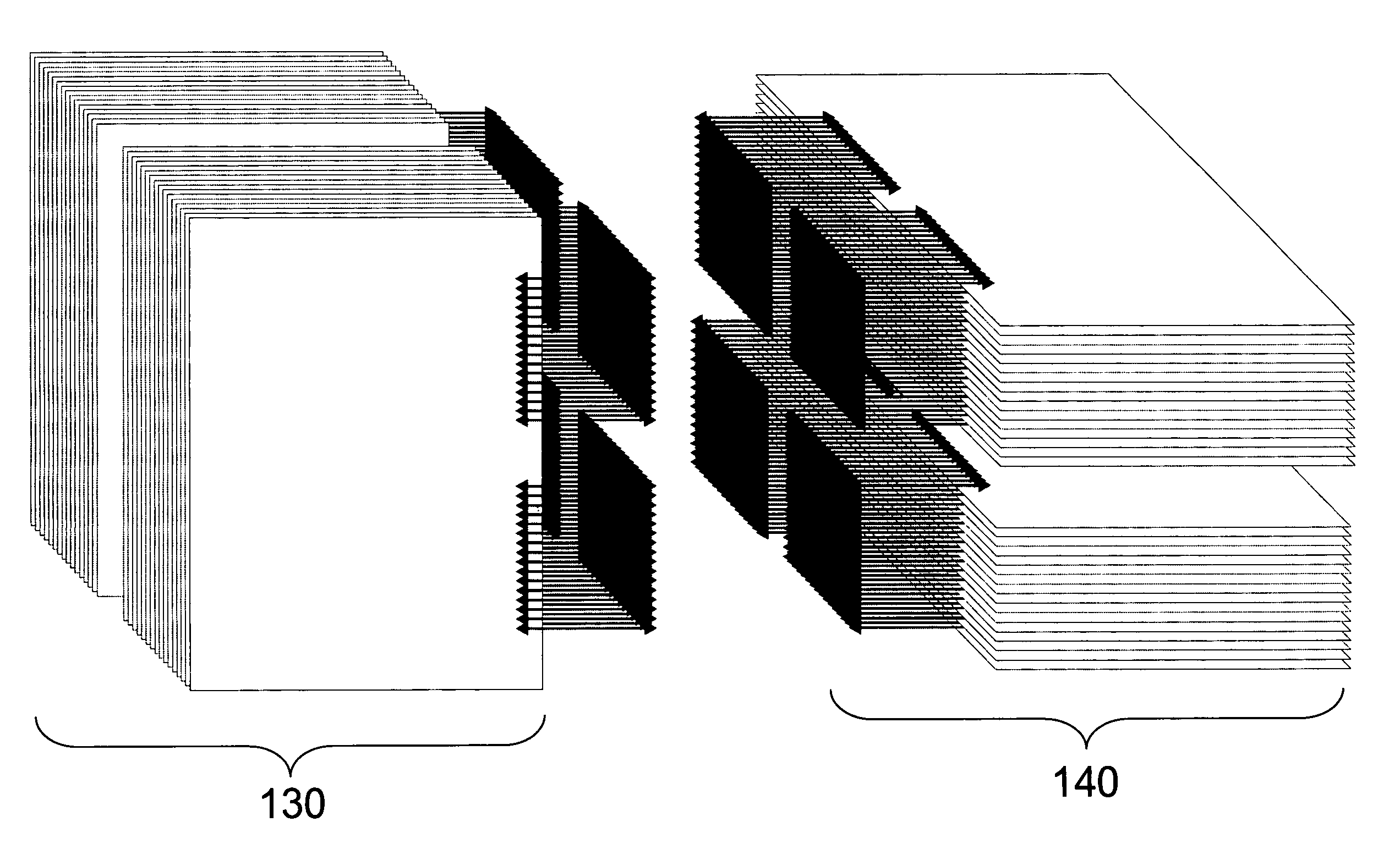
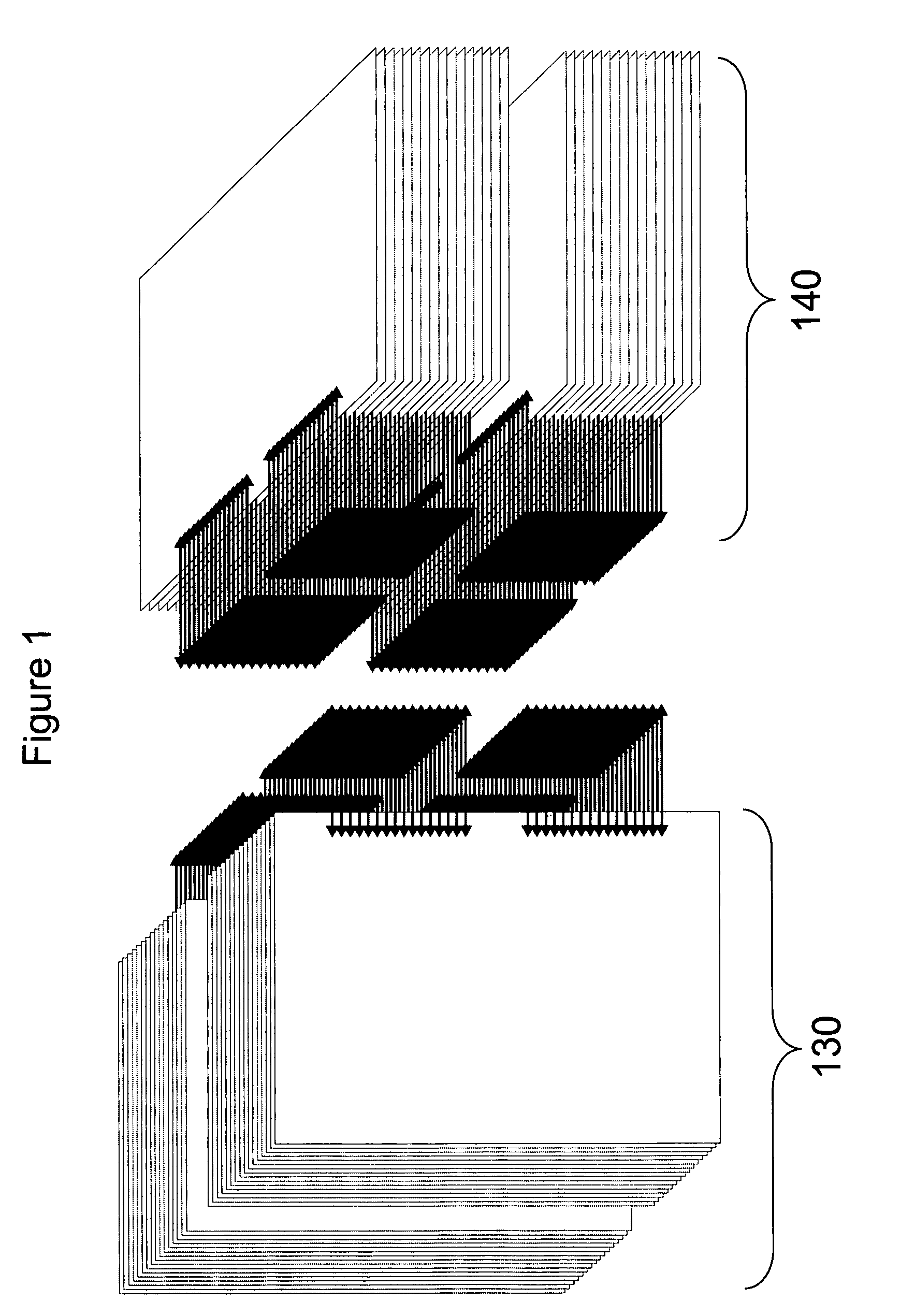
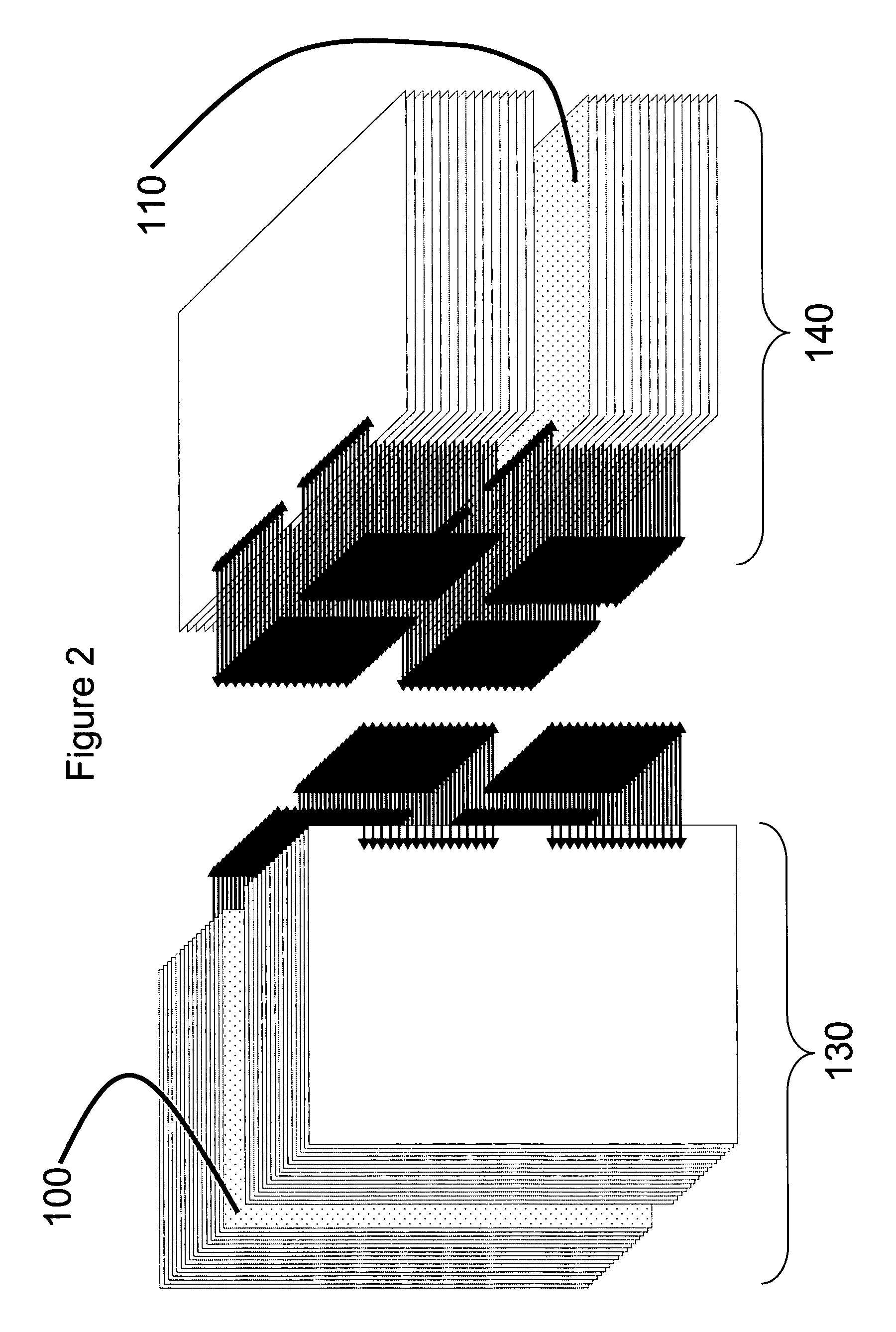
[0017]FIG. 2 illustrates a control plane architecture for an orthogonal system architecture according to an embodiment of the present invention. Preferably, the control plane architecture of this embodiment includes a first control board 100 oriented in the first plane (see vertical first stack 130) and a second control board 110 oriented in the second plane (see horizontal second stack 140). The control boards 100, 110 can be oriented at substantially a midpoint of their respective stacks 130, 140, or at some other location within the stacks 130, 140 as would be understood by those of skill in the art after reading this disclosure. The remaining boards in first stacks 130, 140 prefe...


PUM


Abstract

A method of and architecture for controlling board elements in an orthogonal system architecture is provided. The method and architecture preferably utilize an internal bus architecture between control boards, such that a first control board can access board elements in its stack via I / O on a second control board and the second control board can access board elements in its stack via I / O on the first control board. Most preferably the internal bus architecture is a HyperTransport bus architecture.

Description

RELATED APPLICATIONS[0001]This invention claims the benefit of and priority to U.S. Provisional Patent Application No. 60 / 899,875, the entire contents of which are incorporated by reference herein in its entirety.FIELD OF THE INVENTION[0002]This invention relates generally to orthogonal system architectures which preferably employ at least two substantially identical stacks of board elements, one stack being orientated in the substantially horizontal plane, and one stack being orientated in the substantially vertical plane, the stacks being interconnected directly using connector technology. More specifically, this invention relates to a control plane architecture for use in an orthogonal system architecture, the control plane architecture comprising at least one control board per stack of board elements with an internal bus architecture extending between control boards of different stacks.BACKGROUND OF THE INVENTION[0003]Computer systems are well known in the art. One example of su...

Claims


Application Information

Patent Timeline
Patent Type & Authority Patents(United States)
IPC IPC(8): G06F13/40
CPCG06F13/409
Inventor KOWALSKI, BOBBY JIMDENNY, RONALD R.
Owner GENERAL DYNAMICS ADVANCED INFORMATION SYST INC
Why Eureka
Try Eureka