E-plane bending rectangular waveguide adjustable filter based on hypertransport membrane
Active Publication Date: 2017-07-07
XIDIAN UNIV
View PDF5 Cites 2 Cited by
Summary
Abstract
Description
Claims
Application Information
AI Technical Summary
This helps you quickly interpret patents by identifying the three key elements:
Problems solved by technology
Method used
Benefits of technology
Problems solved by technology
For example, in 2016, Werner A. Arriola published an article titled "Bandwidth of Complementary Split Ring Resonator for Rectangular Waveguide BPFs" in "IEEE MICROWAVE AND WIRELESS COMPONENTS LETTERS", the international issue number is ISSN 1531-1309. A structure in which a slotted ring is inserted into a rectangular waveguide is proposed. By changing the position of the slot on the slotted ring, several different filtering bandwidths can be realized with the center frequency unchanged. The 3dB passband bandwidth can be realized from 3.2 % to 31% discrete control, but the structure cannot achieve continuous regulation of the passband bandwidth, and the amount of change in the passband bandwidth is limited
[0005] Although the above prior art can realize the effective design of rectangular waveguide tunable filters, since these rectangular waveguide tunable filters mostly adjust the center frequency, although the passband bandwidth can also be adjusted, the amount of adjustment is very limited, and many It is discretely adjusted, and it is difficult to achieve continuous dynamic adjustment
With the development of science and technology, the requirements for microwave communication systems are getting higher and higher, and microwave communication has different requirements for filter passband bandwidth, so the application range of existing rectangular waveguide tunable filters is limited
Method used
Image
Click on the blue label to locate the original text in one second.
Reading with bidirectional positioning of images and text.
Examples
Embodiment 1
[0024] Example 1, a rectangular waveguide tunable filter bent at 60°.
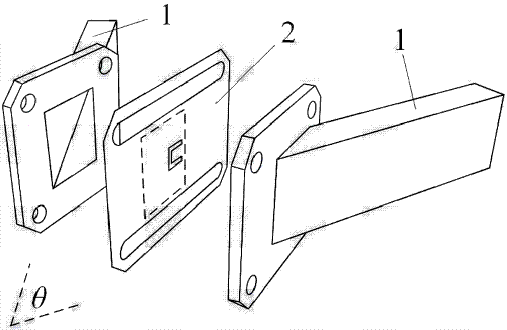
[0025] This example includes a rectangular waveguide 1 and a super transmission diaphragm 2.
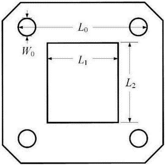
[0026] The rectangular waveguide 1 uses a standard WR90 waveguide with a length of 22.86mm, a width of 10.16mm, and a working frequency range of 8.2GHz-12.4GHz. It adopts an E-plane bending structure with a bending angle of θ=60°. There are two rectangular flanges at the bend. The plane of each flange is inclined to the plane of the broad side of the waveguide, and the four corners are provided with through holes, such as figure 2 As shown, the four through holes of each flange are of equal size, with a diameter of W 0 =5mm, the length L between the upper two through holes 0 =32mm, the cross-sectional width L of the rectangular waveguide at the bend 1 =10.16 / sin(θ / 2)=20.32mm, height L 2 = 22.86mm.
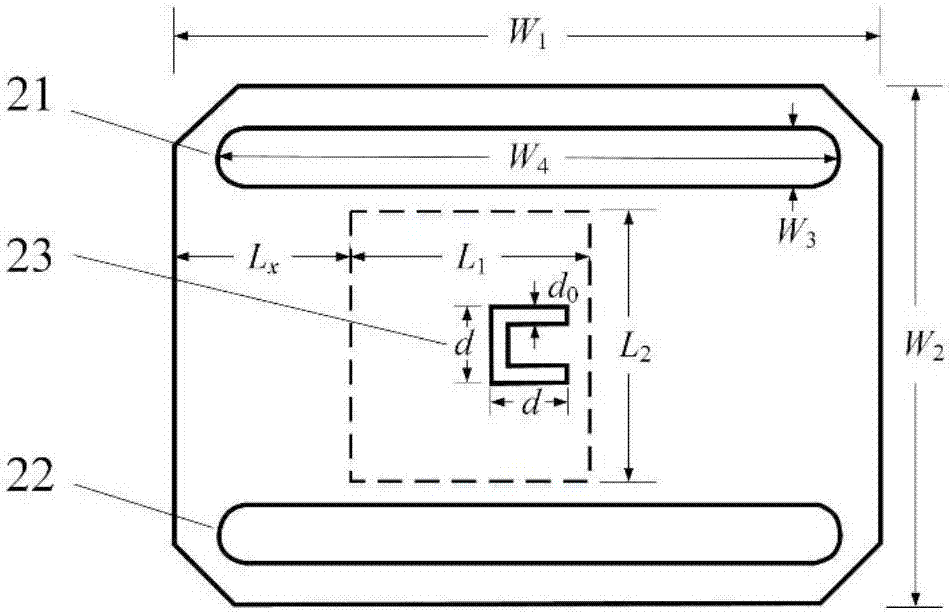
[0027] The super transmission diaphragm 2 is located at the bend of the E surface of the rectangular waveguide, such as ...
Embodiment 2
[0030] Embodiment 2, a rectangular waveguide tunable filter bent at 90°.
[0031] In this example, assume that the bending angle of the E-surface bending structure is θ=90°, and the other structures and parameters are the same as those in Example 1. The sliding distance L of the super transmission diaphragm 2 is calculated. x Range is
[0034] In this example, assume that the bending angle of the E-surface bending structure is θ=120°, and the other structures and parameters are the same as those in Example 1, and the sliding distance L of the super transmission diaphragm 2 is calculated. x Range is
[0035] 21.02mm≤L x ≤27.25mm.
[0036] When the bending angle θ of the bending structure on the E surface takes different values, the sliding distance change range ΔL x As shown in Table 1.
[0037] Table 1 The range of sliding distance of the ultra-transmission diaphragm 2 when the bending angle θ takes different values
[0039] It can be seen from Table 1, that the smaller the bending angle θ of the E surface, the smaller the L x The larger the value range of is, the adjustment range is from 4.66mm to 33.76mm. The technical effect achieved by the present i...
PUM
Abstract
The invention discloses an E-plane bending rectangular waveguide adjustable filter based on a hypertransport membrane. The adjustable filter mainly solves the problem of small adjustment quantity of passband bandwidth of the existing waveguide adjustable filter. The adjustable filter comprises rectangular waveguides (1) and the hypertransport membrane (2), wherein the rectangular waveguides (1) are in E-plane bending structures; two rectangular flange plates are arranged at bending parts; two strip-type through holes (21) and (22) which are parallel are formed in upper and lower positions of the hypertransport membrane (2); a C-shaped gap (23) is arranged in the middle of the hypertransport membrane (2); an opening of the C-shaped gap (23) faces towards inner bending sides of the waveguides; and the hypertransport membrane (2) is fixed between the two rectangular flange plates of the rectangular waveguides (1), and slides along inner and outer bending sides of the waveguides in the two strip-type through holes (21) and (22) to adjust a position of the C-shaped gap (23) and realize continuous adjustment of passband bandwidth. The adjustable filter has the advantages of large adjustment quantity of the passband bandwidth and simple structure, and can be used in the field of microwave communication.
Description
Technical field [0001] The invention belongs to the field of microwave technology, and particularly relates to a rectangular waveguide tunable filter, which can be used for microwave communication. [0002] technical background [0003] Rectangular waveguide tunable filter is an important microwave device used to separate signals of different frequencies. Its main function is to suppress unwanted frequency signals so that they cannot pass through the filter and only allow the required frequency signals to pass. The center frequency or The passband bandwidth can be adjusted according to requirements. It has the characteristics of low insertion loss, good temperature stability and large power capacity. It is widely used in satellite communications, electronic countermeasures and radar systems. [0004] The common adjustment method of rectangular waveguide tunable filter is to add a tuning screw in the filter, and realize the purpose of continuously adjusting the center frequency of the...
Claims
Application Information
Patent Timeline
Application Date:The date an application was filed.
Publication Date:The date a patent or application was officially published.
First Publication Date:The earliest publication date of a patent with the same application number.
Issue Date:Publication date of the patent grant document.
PCT Entry Date:The Entry date of PCT National Phase.
Estimated Expiry Date:The statutory expiry date of a patent right according to the Patent Law, and it is the longest term of protection that the patent right can achieve without the termination of the patent right due to other reasons(Term extension factor has been taken into account ).
Invalid Date:Actual expiry date is based on effective date or publication date of legal transaction data of invalid patent.