Eureka AIR delivers breakthrough ideas for toughest innovation challenges, trusted by R&D personnel around the world.

Dry sprinkler

a technology of dry sprinklers and sprinklers, applied in fire rescue and other directions, can solve the problems of failure of dry sprinklers, and increased occupancy hazards beyond initial system capability, and achieve the effect of improving the performance of dry sprinklers and reducing the risk of fir

Inactive Publication Date: 2010-09-28
TYCO FIRE PRODS LP
View PDF32 Cites 21 Cited by
  • Summary
  • Abstract
  • Description
  • Claims
  • Application Information

AI Technical Summary

Problems solved by technology

Failures of such systems may occur when the system has been rendered inoperative during building alternation or disuse, or the occupancy hazard has been increased beyond initial system capability.
Although the known dry sprinklers have employed a metallic disc annulus to utilize the axial thrust that it creates to translate the closure assembly within the passageway, the arrangement of components, including the metallic disc annulus, has been found to be inadequate for the performance of the dry sprinkler.
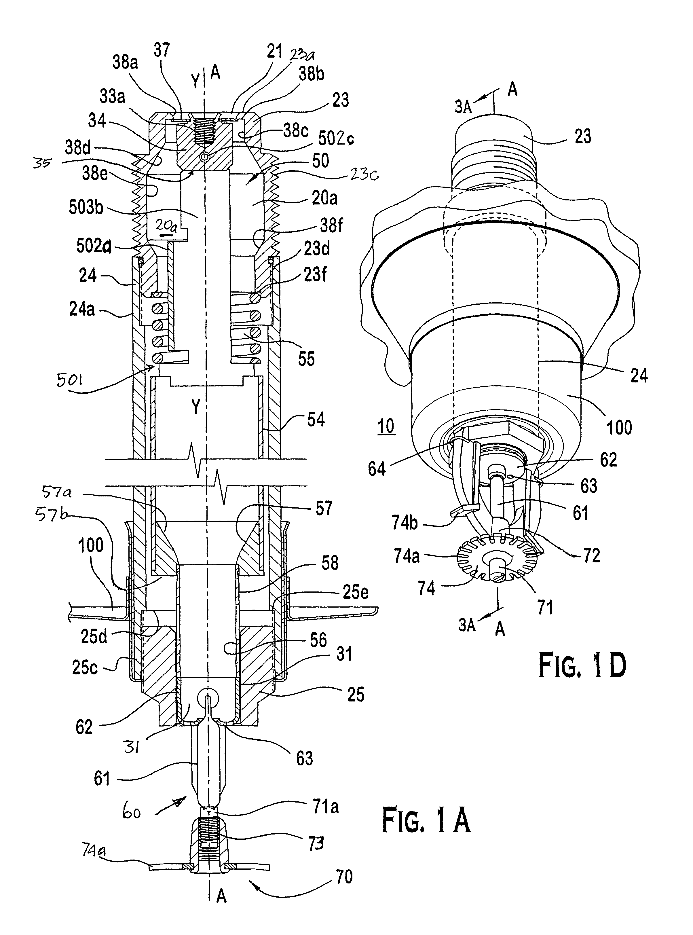
Specifically, the inventors have discovered that the known arrangements of components translate the metallic disc annulus along the passageway, however, these arrangements of components appear to maintain an orientation of the central axis of the metallic disc annulus along the longitudinal axis of the dry sprinkler such that the known dry sprinklers fail to achieve their expected performance.
The known dry sprinklers, however, provide an actual flow rate from the outlet at less than an acceptable tolerance level.

Method used


Image

  • Dry sprinkler
  • Dry sprinkler
  • Dry sprinkler

Examples


first embodiment

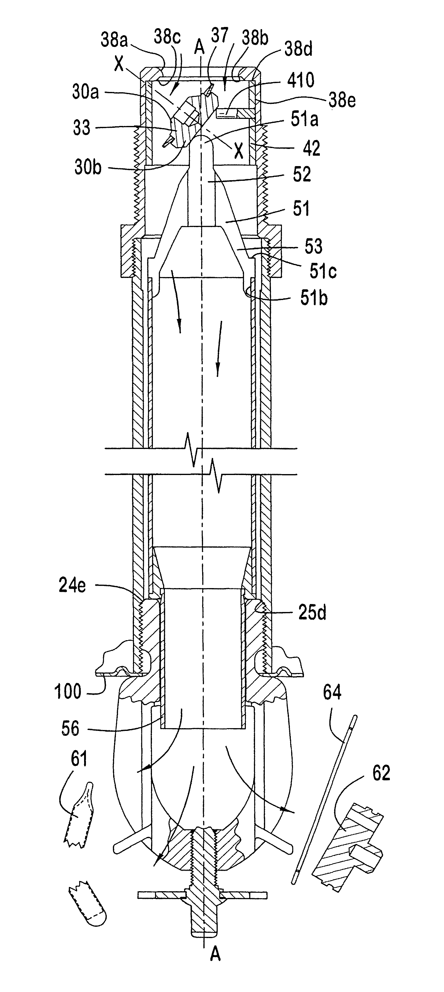
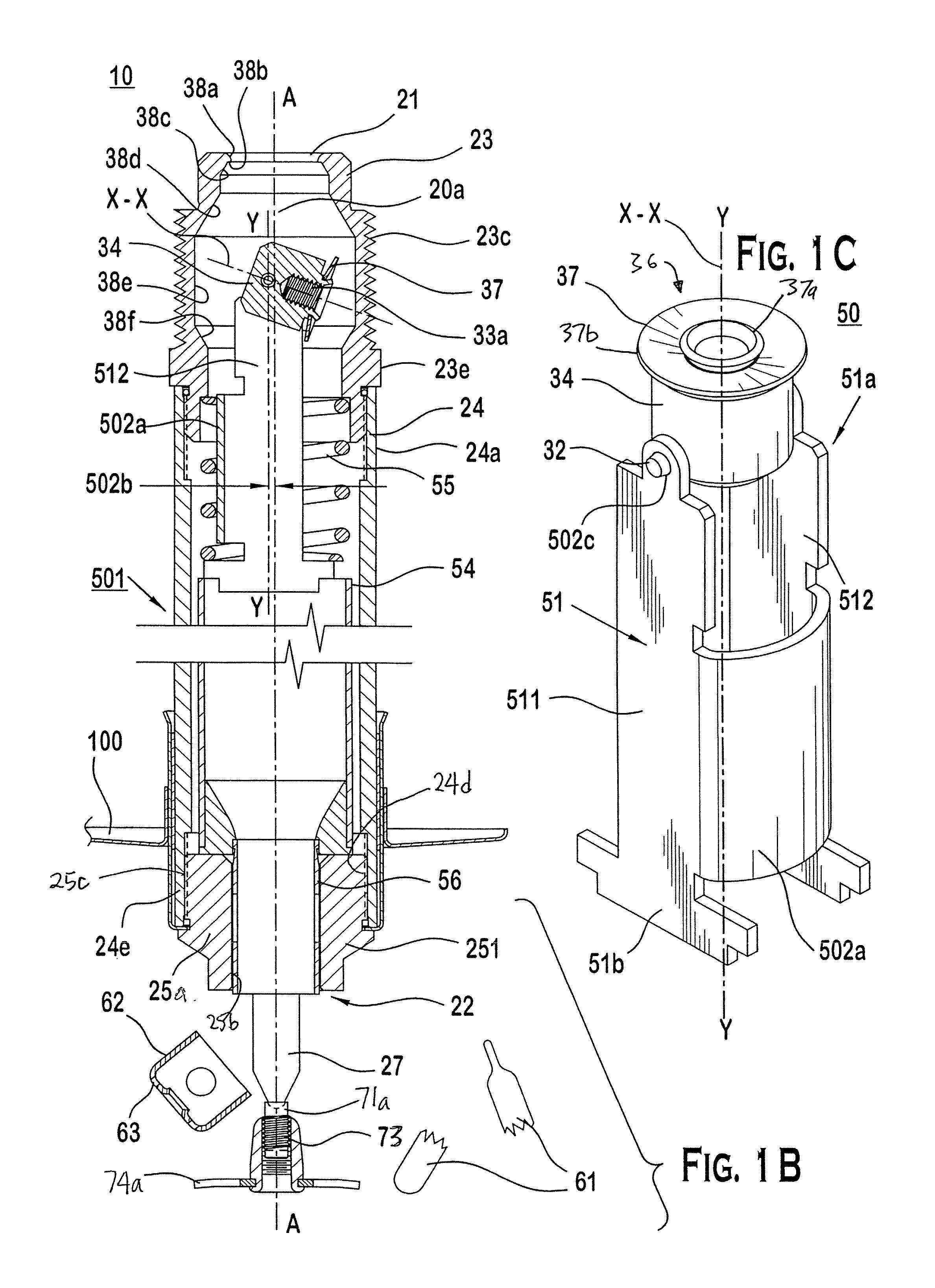
[0100]In a second preferred embodiment of the dry sprinkler, as shown in FIGS. 2A-2D, a second arrangement of the locator 50 is provided for repositioning of the face 37 so that the central axis X-X of the face 37 is skewed to the longitudinal axis A-A in an actuated condition of the dry sprinkler 10 and the expected flow rate is provided from the dry sprinkler. In particular, while the closure assembly 30 is similar to that of the first embodiment, the inner assembly 501 includes a multi-legged yoke 51 that extends along a yoke axis Y-Y and coupled to a fluid tube 54 and guide tube 56. The yoke 51 provides a mounting point for pin 32 to intersect generally transverse to the longitudinal axis A-A so that the closure assembly 30 can be mounted to the yoke 51 via legs 36 (FIG. 2D). The yoke 51 has a first support end 51a coupled to the closure assembly 30 through pin 32 and a second support end 51b coupled to the fluid tube 54. The first yoke support end 51a has at least one elongate ...

third embodiment

[0116]The fourth preferred embodiment can be assembled in a similar manner as described above in relation to the

[0117]In operation, when the dry sprinkler is actuated so that the locator 50 is translated from the first position to the second position, the closure assembly 30 is generally moved or flipped to one side of and along the longitudinal axis A-A to permit water to flow through the inlet and from the outlet at the expected flow rate.

[0118]Referring to the fifth preferred embodiment, as shown in FIGS. 5A-5F, yet another arrangement of the locator 50 is provided for repositioning of the face 37 so that the central axis X-X of the face 37 is skewed to the longitudinal axis A-A in an actuated condition of the dry sprinkler 10 and the expected flow rate is provided from the dry sprinkler. With reference to FIGS. 5B and 5D, the contact member 40 is a tubular bar 412 offset relative to the longitudinal axis A-A, and the tubular bar has a contact surface 412a that extends generally ...


PUM


Abstract

A dry sprinkler for a fire protection system. The preferred dry sprinkler has a metallic disc annulus positionable within a passageway to skew a central axis of a face of the metallic disc annulus with respect to a longitudinal axis of the dry sprinkler so that an expected minimum flow rate based on a rated discharge coefficient is provided. The dry sprinkler operates to provide an expected flow rate over a range of start pressures. The expected flow rate is based on a K-factor rating. The dry sprinkler provides an acceptable level of fluid flow rate from the expected flow rate based on the K-factor for a range of start pressures.

Description

PRIORITY[0001]This application is a continuation of U.S. patent application Ser. No. 10 / 622,631, filed Jul. 21, 2003 which claims the benefits of priority under 35 U.S.C. §119 of Provisional Patent application Ser. No. 60 / 396,727 filed on 19 Jul. 2002, entitled, Dry Sprinkler; Provisional Patent application Ser. No. 60 / 427,214 filed on 19 Nov. 2002, entitled Dry Sprinkler With a Contact Member to Assist Movement of a Closure Member; Provisional Patent application Ser. No. 60 / 432,998 filed on 13 Dec. 2002, entitled Dry Sprinkler With a Contact Member to Assist Rotation of a Closure Assembly; Provisional Patent application Ser. No. 60 / 432,995 filed on 13 Dec. 2002, entitled Dry Sprinkler With a Contact Bar to Assist Rotation of a Closure Assembly; Provisional Patent application Ser. No. 60 / 432,996 filed on 13 Dec. 2002, entitled Dry Sprinkler with Bearing to Assist Rotation of a Closure Assembly; Provisional Patent application Ser. No. 60 / 433,611 filed on 16 Dec. 2002, entitled Dry Sp...

Claims


Application Information

Patent Timeline
Patent Type & Authority Patents(United States)
IPC IPC(8): A62C37/08A62C35/00A62C35/62
CPCA62C37/14A62C35/68A62C35/62A62C37/11
Inventor SILVA, JR., MANUEL R.ARCHIBALD, THOMAS E.POUNDER, DONALD B.
Owner TYCO FIRE PRODS LP
Why Eureka
Eureka Blog
Learn More