
Self-adjusting wrench

a self-adjusting, wrench technology, applied in the field of wrenches, can solve the problems of design limitations, inconvenient use of wrenches, etc., and achieve the effect of limiting the extent of relative movement and limiting the compression of resilient members

Inactive Publication Date: 2010-10-05
STANLEY WORKS THE
View PDF85 Cites 10 Cited by
  • Summary
  • Abstract
  • Description
  • Claims
  • Application Information

AI Technical Summary

Benefits of technology

[0011]An aspect of the present invention is to provide an open-end wrench including a handle portion and a containing portion. The containing portion includes a first jaw and a second jaw. The jaws define a containing groove configured to receive a workpiece. The open-end wrench also includes a chuck base, a resilient member and a stop protector. The chuck base is slidably mounted on the second jaw. The resilient member is operatively disposed between the second jaw and the chuck base. The resilient member is configured to bias the chuck base towards the handle. The protector stop interacts between the second jaw and the chuck base to limit the extent of relative movement therebetween to limit the extent of compression of the resilient member.

Problems solved by technology

While some designs for open-ended wrenches are available, these designs have some limitations.
Therefore, the wrench 10 can be inconvenient to use.

Method used


Image

  • Self-adjusting wrench
  • Self-adjusting wrench
  • Self-adjusting wrench

Examples


Embodiment Construction

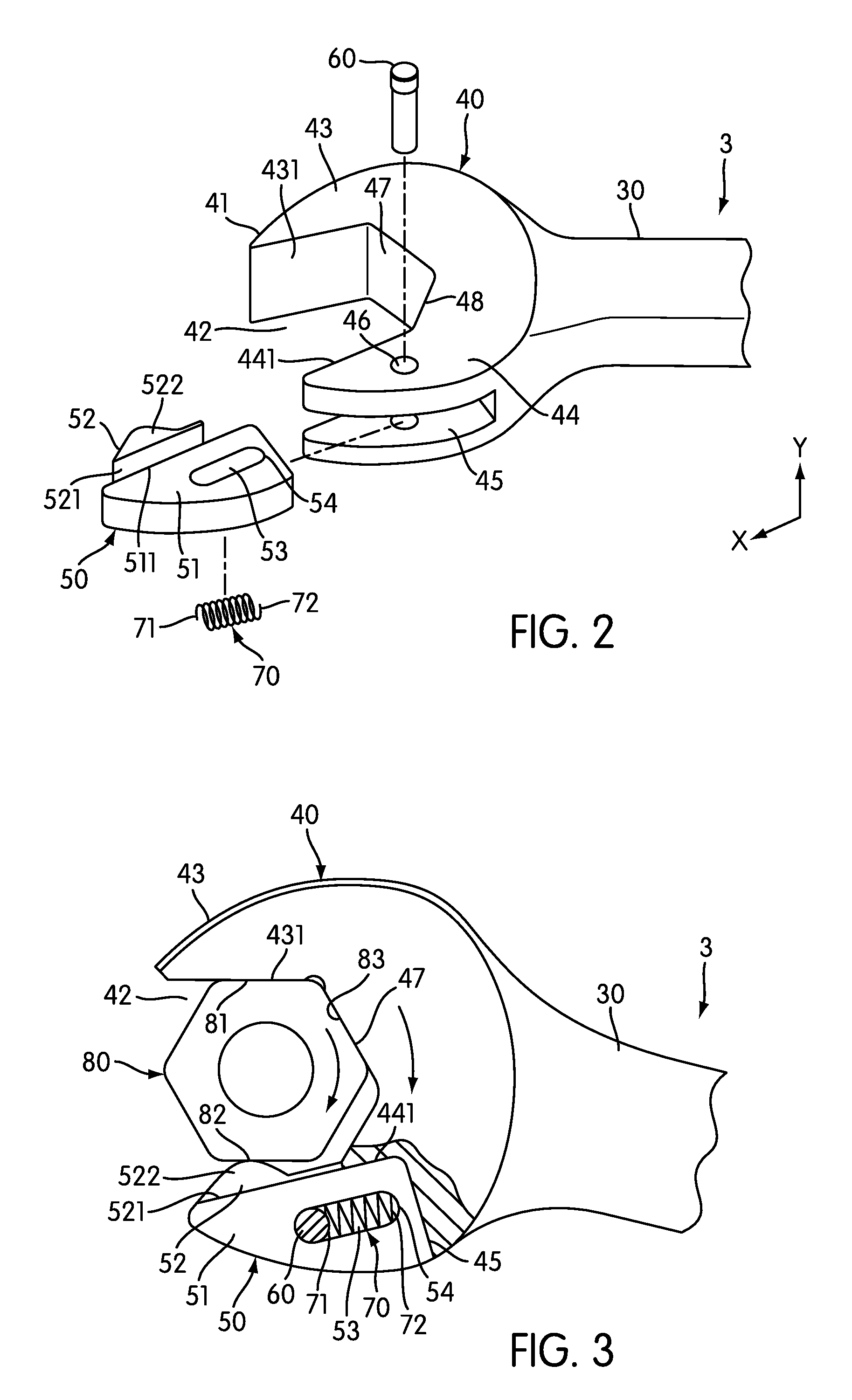
[0021]FIG. 2 is an exploded perspective view of an open-end wrench 3, according to an embodiment of the present invention and FIG. 3 is a combined elevational view and broken away sectional view of the open-end wrench 3. Open-end wrench 3 comprises a handle 30, a containing part 40, a chuck base 50, a dowel pin 60 and a resilient member 70.

[0022]The containing part 40 can be provided on one side of the handle 30 or on both sides of the handle 30. As used herein, the term containing part refers broadly to the open-ended region of an open ended wrench that receives a fastener or nut. In one embodiment, the containing part 40 includes containing groove 42 having an outer surface 41 which contacts handle 30. The containing groove 42 is configured to receive nut-locking component 80. The containing part 40 also includes a first jaw 43 and a second jaw 44 on opposite sides of containing groove 42. A sliding groove 45 is provided in the second jaw 44 along a first direction X. The sliding ...


PUM


Abstract

An open-end wrench includes a handle portion and a containing portion. The containing portion includes a first jaw and a second jaw. The jaws define a containing groove configured to receive a workpiece. The open-end wrench also includes a chuck, a resilient member and a stop protector. The chuck is slidably mounted on the second jaw. The resilient member is operatively disposed between the second jaw and the chuck. The resilient member is configured to bias the chuck towards the handle. The protector stop interacts between the second jaw and the chuck to limit the extent of relative movement therebetween to limit the extent of compression of the resilient member.

Description

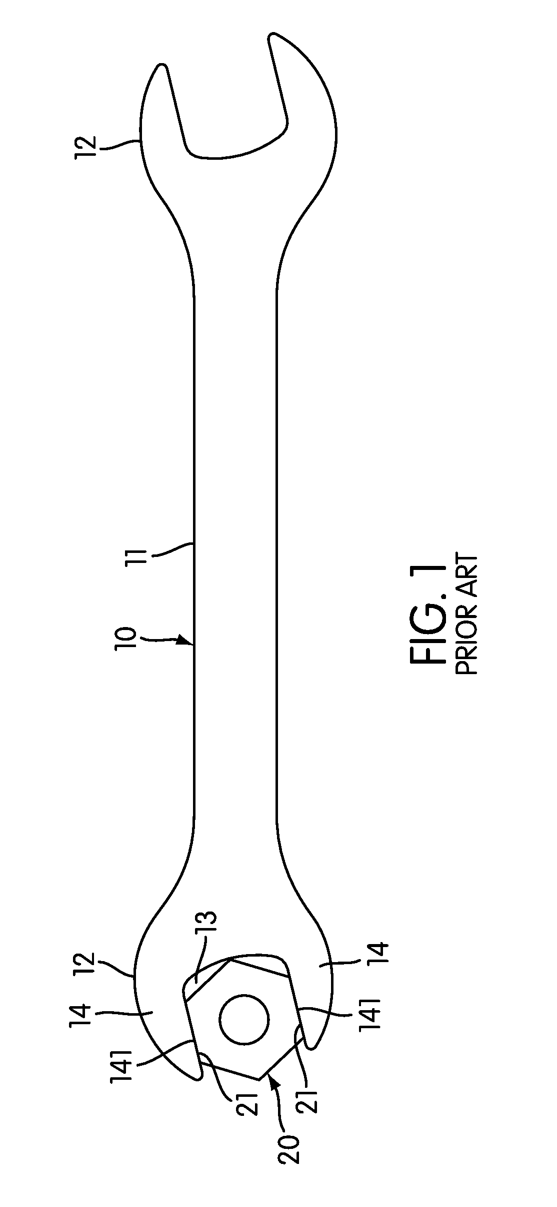
[0001]The present Patent Application is based on and claims priority to Patent Application No. 096130110, filed in China on Aug. 15, 2007, the entire contents of which is hereby incorporated by reference.BACKGROUND OF THE INVENTION[0002]1. Field of the Invention[0003]The present invention pertains to wrenches and more particularly to a self-adjusting wrench.[0004]2. Discussion of Related Art[0005]Various wrenches are known. Some wrenches are closed-end wrenches, that is wrenches that encompass the circumference of a workpiece. In some circumstances, due to tight working quarters for example, use of a closed-end wrench to drive a workpiece may be precluded. As an alternative to a closed-end wrench, an open-ended wrench may be used.[0006]While some designs for open-ended wrenches are available, these designs have some limitations.[0007]FIG. 1 is an elevational view of a conventional open-end wrench. As shown in FIG. 1, conventional open-end wrench 10 has a handle 11 and two containing...

Claims


Application Information

Patent Timeline
Patent Type & Authority Patents(United States)
IPC IPC(8): B25B13/12
CPCB25B13/08B25B13/46
Inventor XINHONG, ZHOU
Owner STANLEY WORKS THE
Learn More