Coating machine and rotary atomizing head thereof

a technology of atomizing head and coating machine, which is applied in the direction of coatings, burners, artistic surface treatment, etc., can solve the problems of increasing the generation amount of scattering coating mist, increasing the consumption amount of energy, and lowering production efficiency, so as to reduce the waste of coating material, improve the deposition efficiency, and save energy consumption

Active Publication Date: 2010-10-05
TRINITY IND CORP
View PDF11 Cites 1 Cited by
  • Summary
  • Abstract
  • Description
  • Claims
  • Application Information

AI Technical Summary

Benefits of technology

[0012]According to the coating machine of the invention, upon supplying a coating material while rotating the rotary atomizing head to a coating material chamber formed at the rear side thereof, the coating material is caused to spread to the peripheral surface of the coating material chamber by a centrifugal force.
[0013]In the rotary atomizing head, since a plurality of rims are fitted being overlapped each at a predetermine clearance in the coating material chamber and the clearance for each of the rims is opened and formed to the peripheral surface of the coating material chamber, the coating material spread to the peripheral surface of the coating chamber is caused to flow into the clearance for each rim and spread.
[0014]Accordingly, in a case where the amount of the coating material supplied to the coating material chamber is constant, the amount of the coating material supplied per one rim is decreased in inverse proportion to the number of rims and, in a case where the rims are overlapped, for example, by the number of four, the amount of the coating material supplied per one rim is decreased to ¼.
[0015]In this case, since the amount of the coating material supplied per one rim is small, even when the number of rotation of the rotary atomizing head is set relatively lower, coating material particles can be atomized to an ideal particle size of 20 to 30 μm.
[0016]Further, while the jetting amount of the coating material per one rim is decreased, for example, to ¼, since the rims are disposed by the number of five, the entire setting amount of the coating material can be ensured.
[0017]As described above, since atomization can be conducted while lowering the number of rotation, it can provide an excellent effect capable of suppressing the coating material mist from scattering to improve the deposition efficiency, decreasing the wasteful loss of the coating material to abate the VOC to be discarded, and saving the energy consumed for combustion treatment thereof, etc, to suppress the occurrence of CO2 and, at the same time, capable of ensuring a necessary jetting amount for maintaining the necessary production efficiency since a plurality of rims are overlapped.

Problems solved by technology

However, increase of the rotational speed not only increases the generation amount of scattering coating mist but also increases the consumption amount of the energy, and this is contrary to the demand for the abatement of the VOC and CO2.
However, no necessary jetting amount can be obtained in this case to result in a problem that a coating film of a necessary thickness can not be formed within a restricted coating time to a work such as car bodies conveyed continuously on a conveyor thereby lowering the production efficiency.

Method used


Image

  • Coating machine and rotary atomizing head thereof
  • Coating machine and rotary atomizing head thereof
  • Coating machine and rotary atomizing head thereof

Examples


Embodiment Construction

[0018]In this embodiment, the subject of atomizing a coating material to improve the deposition efficiency without lowering the production efficiency thereby abating the VOC and CO2 has been attained by providing a plurality of rims to the rotary atomizing head for rotationally atomizing the coating material.

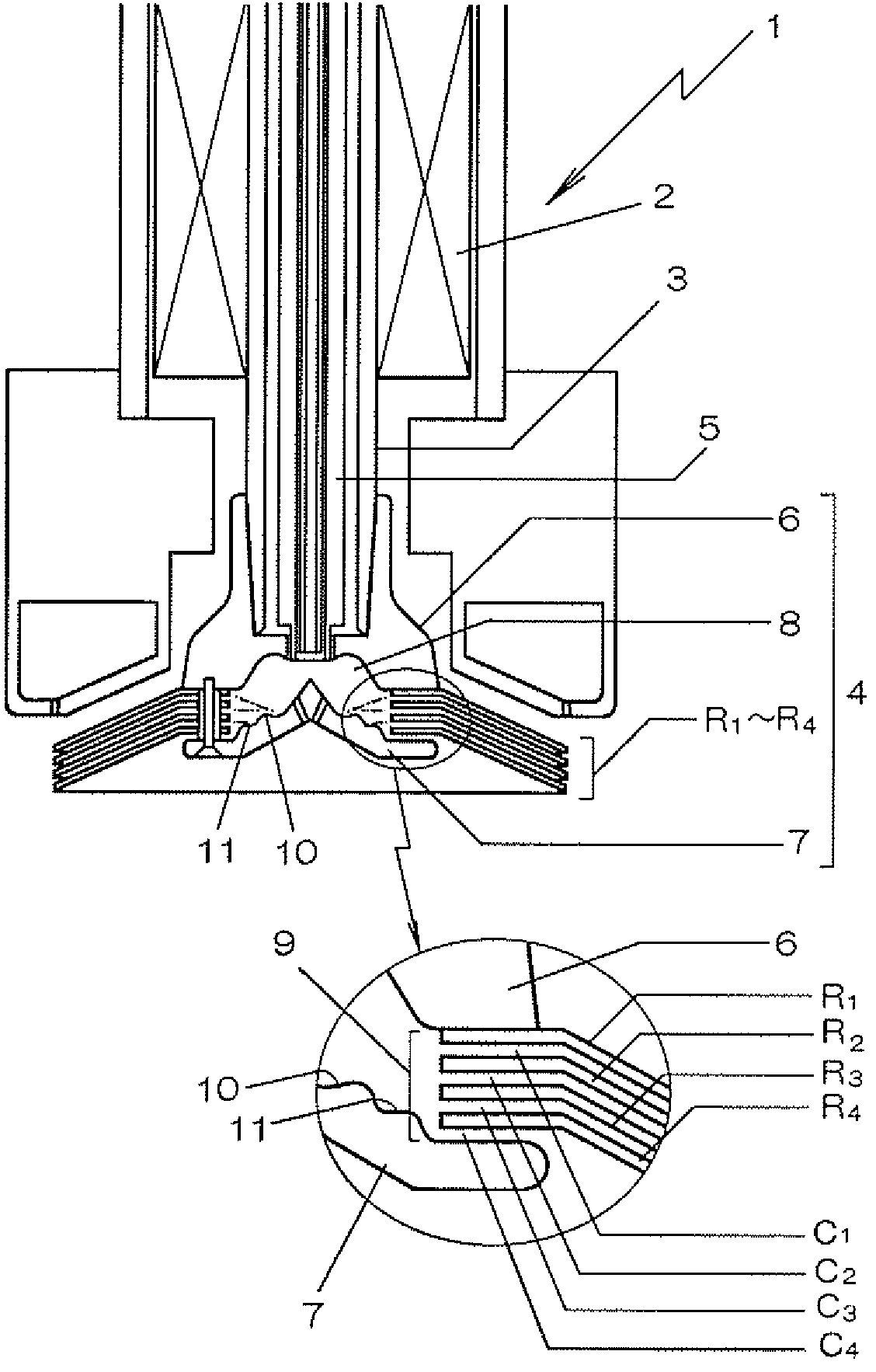
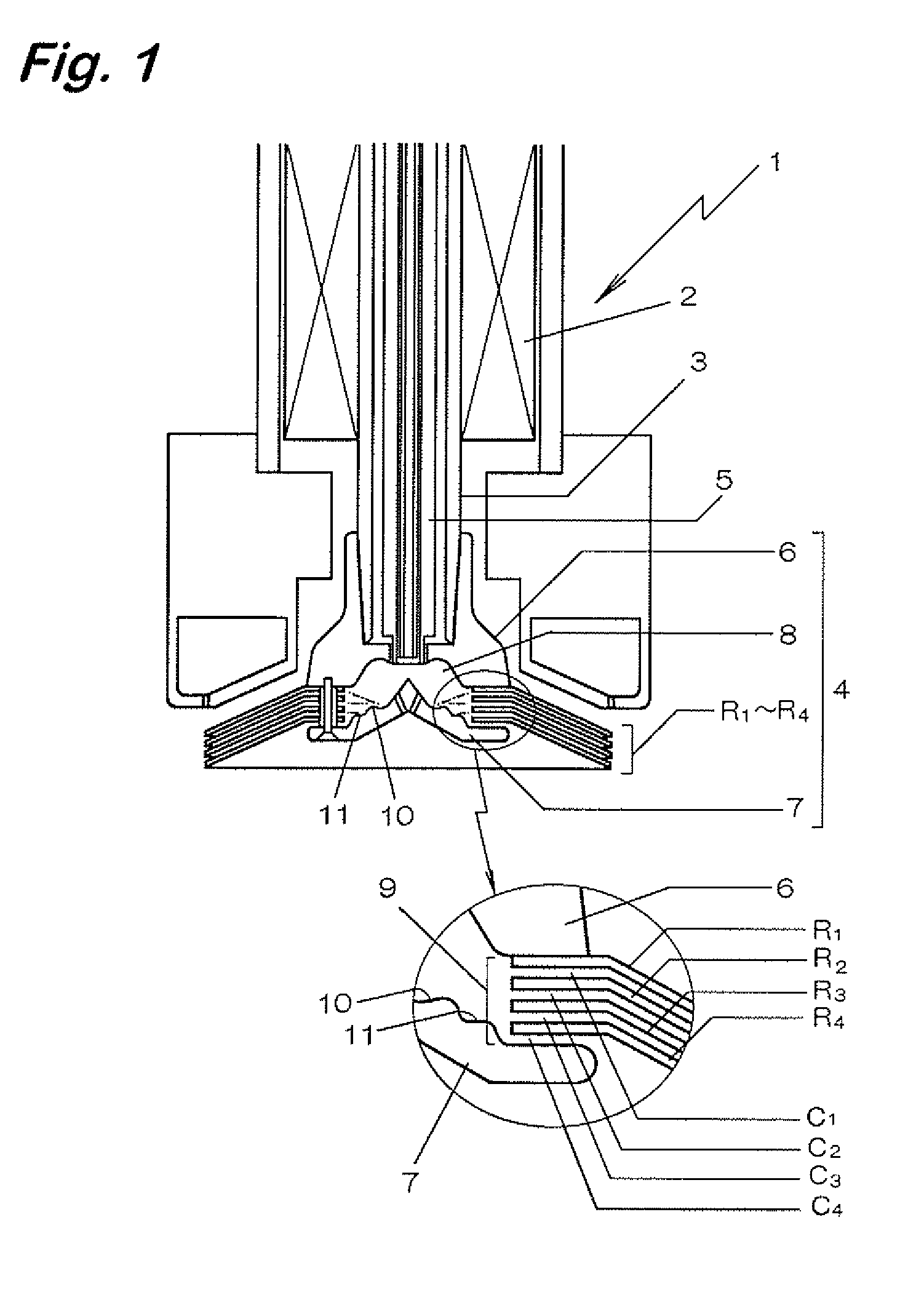
[0019]FIG. 1 is an explanatory view showing an example of a coating machine according to this invention.

[0020]A coating machine 1 shown in FIG. 1 is a center feed type rotary atomizing electrostatic coating machine in which a rotary atomizing head 4 is fitted to the top end of a tubular rotary shaft 3 of a built-in air motor 2, and a coating material supplied from the fine tubular nozzle 5 inserted through the tubular rotary shaft 3 to the rotary atomizing head 4 is deposited to a work by an electrostatic force.

[0021]In the rotary atomizing head 4, an inner bell 7 is provided on the frontal side of a bell main body 6 fitted to the tubular rotary shaft 3, a coating material chamb...


PUM


Abstract

A coating machine is capable of reducing VOC and CO2 by atomizing a paint to increase depositing efficiency without lowering production efficiency and the rotary atomizing head of the coating machine. The coating machine includes the rotary atomizing head in which a paint chamber receiving the supply of paint is formed on the rear side thereof. A plurality of rims formed in a roughly truncated conical shape for extending the paint flowing out of the paint chamber by a centrifugal force and atomizing the paint at the tip thereof are fitted in the rotary atomizing head overlappingly at specific clearances. The clearances are opened to the peripheral surface part of the paint chamber. Accordingly, VOC and CO2 can be reduced by reducing the total jetted amount of paint to enable the atomization of the paint at low rotating speeds so as the increase the deposit efficiency.

Description

TECHNICAL FIELD[0001]The present invention concerns a rotary atomizing type coating machine and a rotary atomizing head using the same.BACKGROUND ART[0002]In an automobile coating line requiring coating at high quality, a rotary atomizing electrostatic coating machine has been popularized since it is excellent in atomizing a coating material and has high deposition efficiency.[0003]FIG. 2 shows such an existent rotary atomizing electrostatic coating machine 21 in which a rotary atomizing head 24 is fitted at the top end of a tubular rotary shaft 23 of a built-in air motor 22.[0004]In the rotary atomizing head 24, a coating material chamber 28 for receiving supply of a coating material from a fine tubular nozzle 27 inserted through the tubular rotary shaft 23 is formed on the rear side of an inner bell 26 fitted to the frontal side of a bell body 25, and a substantially frustconical rim 30 is formed on the frontal side thereof for spreading the coating material jetted out centrifugal...

Claims


Application Information

Patent Timeline
Patent Type & Authority Patents(United States)
IPC IPC(8): B05B3/00B05B3/04B05B3/10F23D11/04
CPCB05B3/1014B05B3/1057B05B3/1064
Inventor NOMURA, TAKAOINADA, SHIGEYOSHIKATSUMATA, TAKASHI
Owner TRINITY IND CORP
Why Eureka
Try Eureka