Illumination device having light guide body

a technology of light guide body and illumination device, which is applied in the direction of lighting and heating apparatus, process and machine control, instruments, etc., can solve the problems of reducing the effect of cost, loss of effective use space, and only a limited use as an independent spot illumination, etc., to reduce the cost, reduce the variance of brightness, and uniform brightness

Inactive Publication Date: 2010-10-05
THE FUJIKURA CABLE WORKS LTD
View PDF14 Cites 6 Cited by
  • Summary
  • Abstract
  • Description
  • Claims
  • Application Information

AI Technical Summary

Benefits of technology

[0011]A first aspect of the illumination device of the present invention is provided with a plurality of light guide bodies, the bottom face of which is given light reflection / scattering treatment, light sources individually connected to the end portions of a plurality of the light guide bodies to radiate the bottom faces of a plurality of the light guide bodies, and a control unit for changing the intensity of light made incident from the light sources to a plurality of the light guide bodies. A plurality of the light guide bodies are laminated so as to be at least partially overlapped at the respective light emitting regions of the light guide bodies, and the control unit allows the intensity of light made incident from the light sources to the light guide bodies to change with the lapse of time.
[0016]A second aspect of the illumination device of the present invention is provided with a plurality of light guide bodies, at least one of the bottom face or the side face of which is given light reflection / scattering treatment, light sources individually connected to the end portions of a plurality of the light guide bodies to radiate the bottom faces or the side faces of a plurality of the light guide bodies, and a control unit for changing the intensity of light made incident from the light sources to a plurality of the light guide bodies. A plurality of the light guide bodies are arrayed so as to be at least partially overlapped at the respective light emitting regions of the light guide bodies, and the control unit allows the intensity of light made incident from the light sources to the light guide bodies to change with the lapse of time.
[0021]According to the illumination device of the present invention, a plurality of the light guide bodies are laminated so as to be at least partially overlapped at the respective light emitting regions of the light guide bodies and the intensity of light made incident from the light sources to a plurality of the light guide bodies is allowed to change with the lapse of time, thus making it possible to provide visual effects of making one-dimensional or two dimensional dynamic changes even by using a smaller number of light sources.
[0022]Further, there is no need for densely disposing many light sources as with a conventional case, thus making it possible to reduce the cost. Still further, a uniform brightness is obtained even when a smaller number of light sources are used, thereby suppressing variance in brightness.

Problems solved by technology

However, the LED, which is a point light source, is of directivity, thus finding only a limited use as an independent spot illumination.
However, this method poses such a problem that the effective use of space is lost.
However, the above method for giving a difference in time interval requires many LEDs densely disposed and also requires a power source for driving each of the LEDs.
For example, if the above method for illuminating the LEDs by turns is used in a case where expressions of relatively simple and patternized motions such as interior signs, indicators of vehicles and displays of signboards are sufficient, the costs to be perform the method reduce the effect.
On the contrary, if an illumination device is lit by using a small number of LEDs for the purpose of reducing the cost, a problem is posed in that no smooth motions are realized or in that brightness varies easily (hereinafter referred to as “variance in brightness”) in an attempt to obtain a uniform distribution of brightness in a static state.
However, this method requires a specific space between the light source and the optical element, consequently contributing to a large-sized illumination device.
Thus, there is provided no solution for removing the disadvantage of higher costs.

Method used


Image

  • Illumination device having light guide body
  • Illumination device having light guide body
  • Illumination device having light guide body

Examples


first embodiment

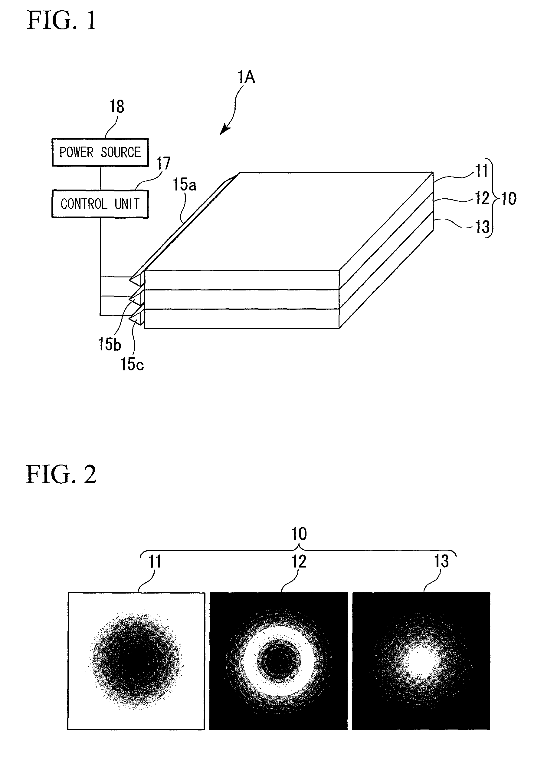
[0030]An explanation will be made for first embodiment of the illumination device of the present invention by referring to FIG. 1 to FIG. 3.

[0031]As shown in FIG. 1 and FIG. 2, the illumination device 1A of the present embodiment is provided with light sources 15a, 15b, 15c such as light emitting diodes (hereinafter abbreviated as “LEDs”) and cold cathode tubes, three (first to third) sheet-like light guide bodies 11, 12 and 13 laminated in the thickness direction, and a control unit 17 for changing the intensity of light made incident from the light sources to the first to the third sheet-like light guide bodies 11, 12 and 13, and connected to a power source 18. The bottom faces of the sheet-like light guide bodies 11, 12 and 13 are given light reflection / scattering treatment, and when light is made incident from the light sources 15a, 15b, 15c connected to the end portion to the sheet-like light guide bodies 11, 12 and 13, the bottom faces of the sheet-like light guide bodies 11, ...

second embodiment

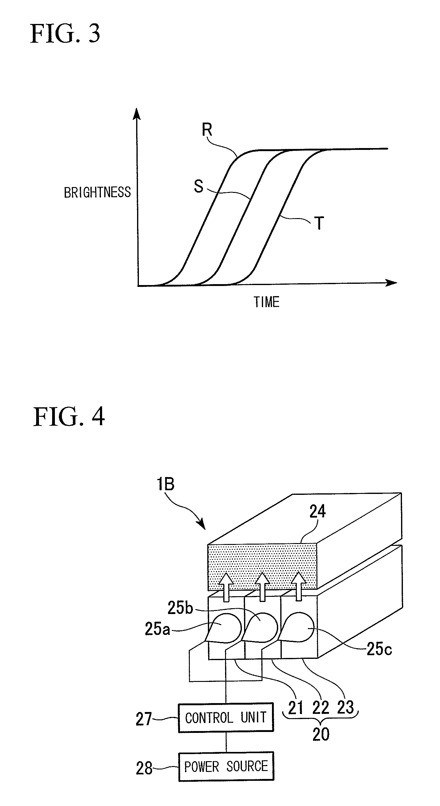
[0046]Next, an explanation will be made for second embodiment of the illumination device of the present invention by referring to FIG. 4. Here, members or parts which are the same as those of first embodiment will be given the same references, an explanation of which will be omitted.

[0047]As shown in FIG. 4, the illumination device 1B of the present embodiment is provided with light sources 25a, 25b, 25c such as LEDs and cold cathode tubes, three (first to third) strip-like light guide bodies 21, 22 and 23 arranged adjacently in the width direction, and a control unit 27 for changing the intensity of light made incident from the light sources to the strip-like light guide bodies 21, 22 and 23, and connected to a power source 28. At least either of the bottom faces or the side faces of the strip-like light guide bodies 21, 22 and 23 are given light reflection / scattering treatment, and when light is made incident from the light sources 25a, 25b, 25c connected to the end portion to the...

example

[0056]An explanation will be made for a more specific example of the present invention by referring to FIG. 5 to FIG. 7. However, the present invention shall not be limited to the following example.

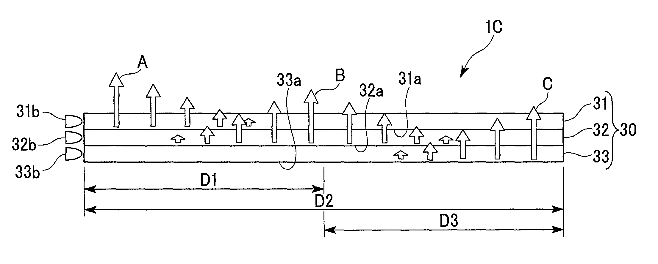
[0057]As shown in FIG. 5, first, three (first to third) strip-like transparent members 31, 32 and 33 made with an acrylic sheet 5 mm in width and 300 mm in length (they are collectively referred to as “strip-like transparent member 30”) are used as the light guide bodies of the illumination device 1C. Screen printing is employed to print white dot patterns in a different gradation on the respective side faces 31a, 32a, 33a of the strip-like transparent members 31, 32 and 33 (bottom faces given in FIG. 5).

[0058]The strip-like transparent members 31, 32 and 33 are laminated, with the respective light-emitting faces placed upward, and white SMD-type light emitting diodes (LEDs) (E1S13-6W0C6-03 made by Toyoda Gosei Co., Ltd.) are connected to the end faces of the strip-like transparent member...


PUM


Abstract

The illumination device is provided with a plurality of light guide bodies, the bottom face of which is given light reflection / scattering treatment, light sources individually connected to the end portions of a plurality of the light guide bodies to radiate the bottom faces of a plurality of the light guide bodies, and a control unit for changing the intensity of light made incident from the light sources to a plurality of the light guide bodies. A plurality of the light guide bodies are laminated so as to be at least partially overlapped at the respective light emitting regions of the light guide bodies, and the control unit allows the intensity of light made incident from the light sources to the light guide bodies to change with the lapse of time.

Description

BACKGROUND OF THE INVENTION[0001]1. Field of the Invention[0002]The present invention relates to an illumination device having a light guide body which serves as a sheet-like or a strip-like light-emitting face.[0003]2. Description of the Related Art[0004]In recent years, there have been frequently used a light emitting diode (hereinafter, sometimes referred to as an “LED”), a cold cathode tube or the like as a light source for illumination due to a higher luminous efficiency. However, the LED, which is a point light source, is of directivity, thus finding only a limited use as an independent spot illumination. The cold cathode tube represented by a fluorescent lamp is used widely as a light source in general. When the cold cathode tube is used as a uniform sheet-like light source, there is adopted a method in which many cold cathode tubes are arranged to have diffusers disposed in front of them. However, this method poses such a problem that the effective use of space is lost.[0005...

Claims


Application Information

Patent Timeline
Patent Type & Authority Patents(United States)
IPC IPC(8): F21V7/04
CPCG02B6/0068G02B6/0076H05B33/0842G02B6/0078H05B45/30
Inventor KAMIKATANO, MITSURUTSUMANUMA, TAKASHI
Owner THE FUJIKURA CABLE WORKS LTD
Why Eureka
Try Eureka