Ultrasonic diagnostic apparatus

a diagnostic apparatus and ultrasonic technology, applied in the field of ultrasonic diagnostic apparatus, can solve the problems of no device in the related art to non-invasively and quantitatively evaluate mechanical characteristics, and achieve the effect of precise shape data

Active Publication Date: 2010-10-05
NAKAMURA KOZO +2
View PDF17 Cites 26 Cited by
  • Summary
  • Abstract
  • Description
  • Claims
  • Application Information

AI Technical Summary

Benefits of technology

[0009]There has been no device in the related art to non-invasively and quantitatively evaluate mechanical characteristics of bone such as bone strength. An advantage of the present invention is that an ultrasonic diagnostic apparatus for non-invasively and quantitatively evaluating mechanical characteristics of bone within a living body is provided.
[0010]According to one aspect of the present invention, there is provided an ultrasonic diagnostic apparatus comprising a transceiver unit which generates a plurality of ultrasonic beams with respect to a bone in a subject and obtains a plurality of echo signals corresponding to the ultrasonic beams; and a shape measurement unit which identifies a surface point corresponding to a bone surface for each of the echo signals and generates shape data of the bone surface based on the plurality of surface points obtained from the plurality of echo signals. According to another aspect of the present invention, it is preferable that the ultrasonic diagnostic apparatus further comprises a characteristic evaluation unit which evaluates a mechanical characteristic of the bone based on a change in the shape data when an external action is applied to the bone.
[0011]With such a structure, it is possible to non-invasively and quantitatively evaluate mechanical characteristics of the bone within a living body from shape data of a bone surface based on the echo signals.
[0012]According to another aspect of the present invention, it is preferable that, in the ultrasonic diagnostic apparatus, the transceiver unit generates the ultrasonic beams within a same cross section of the bone in the subject. According to another aspect of the present invention, it is preferable that, in the ultrasonic diagnostic apparatus, the shape measurement unit comprises a tracking unit which tracks the surface points from a state in which the external action is not applied to a state in which the external action is applied. According to another aspect of the present invention, it is preferable that, in the ultrasonic diagnostic apparatus, the shape measurement unit comprises a shape data generator unit which generates the shape data for each time phase from the state in which the external action is not applied and the state in which the external action is applied.
[0013]With such a structure, the transceiver unit generates ultrasonic beams within the same cross section with respect to a bone in the subject and the bone surface points are tracked. Because of this, a bone surface is always detected within the same cross section during the entire measurement period. Therefore, it is possible to obtain very precise shape data. According to another aspect of the present invention, it is preferable that, in the ultrasonic diagnostic apparatus, the shape data generator unit generates, as the shape data, an interpolation line connecting the plurality of surface points for each time phase. With such a structure, it is possible to evaluate a bone on an arbitrary point on the generated interpolation line.
[0014]According to another aspect of the present invention, it is preferable that, in the ultrasonic diagnostic apparatus, the characteristic evaluation unit overlaps the interpolation line corresponding to the state in which the external action is not applied and the interpolation line corresponding to the state in which the external action is applied by overlapping one of the interpolation lines on the other to correct a displacement due to a movement of the bone between the two interpolation lines and evaluates the mechanical characteristic of the bone based on the two corrected interpolation lines. With such a structure, even when the bone moves with respect to the transceiver unit during measurement, it is possible to evaluate while correcting the displacement due to the movement of the bone.

Problems solved by technology

There has been no device in the related art to non-invasively and quantitatively evaluate mechanical characteristics of bone such as bone strength.

Method used


Image

  • Ultrasonic diagnostic apparatus
  • Ultrasonic diagnostic apparatus
  • Ultrasonic diagnostic apparatus

Examples


Embodiment Construction

[0031]A preferred embodiment of the present invention will now be described referring to the drawings.

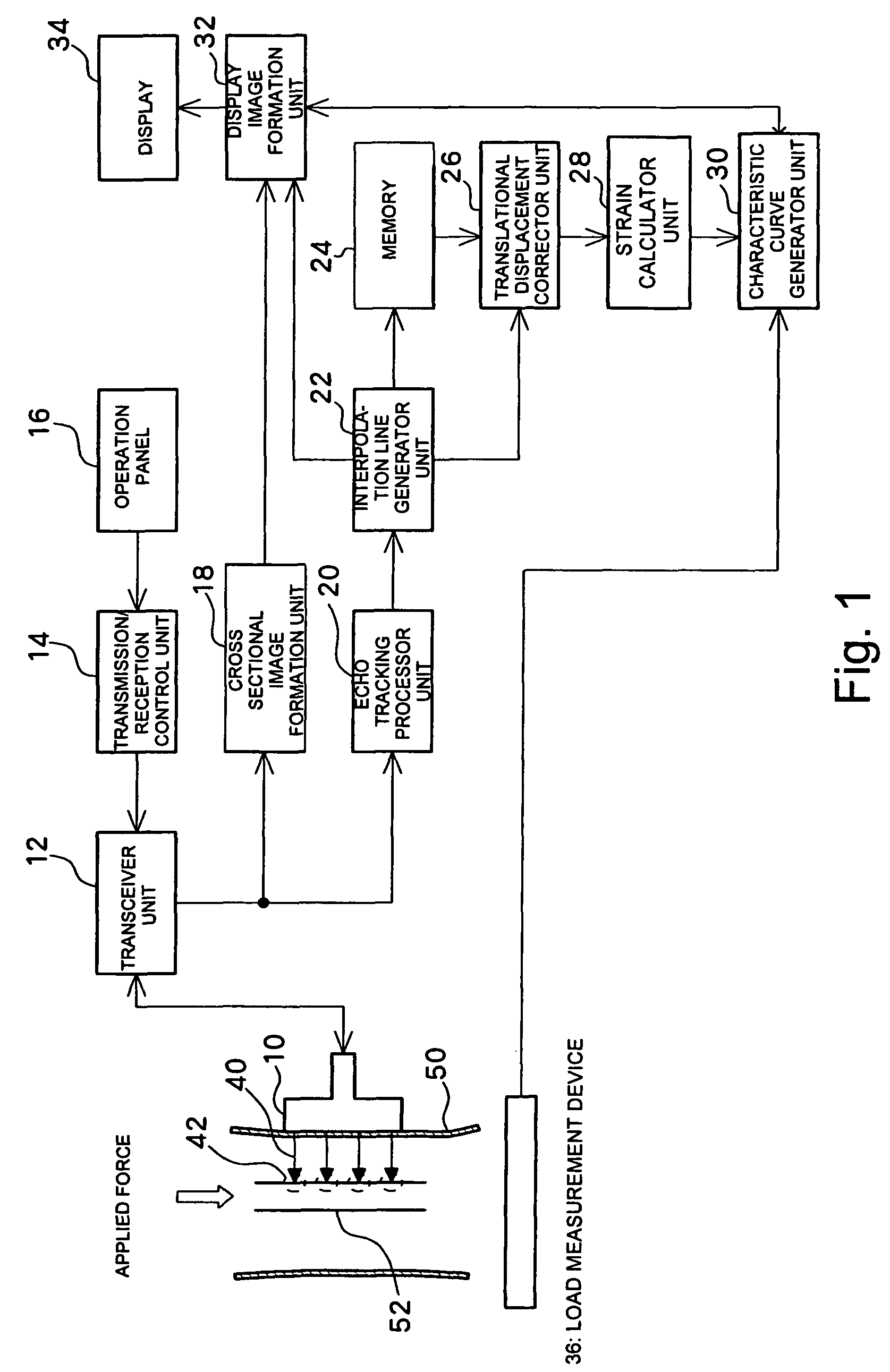
[0032]FIG. 1 shows a preferred embodiment of an ultrasonic diagnostic apparatus according to the present invention. FIG. 1 is a block diagram showing an overall structure of the ultrasonic diagnostic apparatus. A probe 10 is an ultrasonic probe used in contact with a surface of the body of a subject 50. Alternatively, an ultrasonic probe which is inserted into the subject may be used. The probe 10 transmits and receives ultrasonic beams 40 to and from a bone 52 within the body of the subject 50. Tracking points 42 which are set on the bone 52 will be described later. As the probe 10, it is desirable to use a linear electronic scan probe (linear array probe) which electronically scans the ultrasonic beam 40.

[0033]A transceiver unit 12 controls the probe 10 and electronically scans the ultrasonic beam 40 on a cross sectional surface (a cut surface of a subject in FIG. 1). When the pro...


PUM


Abstract

An echo tracking processor unit detects a bone surface section based on an echo signal and tracks a position of the bone surface section. An interpolation line generator unit generates an interpolation line connecting tracking points which represent the tracked bone surface section. A translational displacement corrector unit removes a translational displacement component between an interpolation line corresponding to a time phase of a no-load state stored in a memory and an interpolation line corresponding to a time phase in a loaded state output from the interpolation line generator unit. A strain calculator unit calculates an amount of strain of bone for each time phase and outputs to a characteristic curve generator unit. The characteristic curve generator unit generates a characteristic curve related to the strain of bone based on a load value output from a load measurement device and the amount of strain of bone output from the strain calculator unit.

Description

CROSS-REFERENCE TO RELATED APPLICATION[0001]The entire disclosure of Japanese Patent Application No. 2003-91097 including specification, claims, drawings and abstract is incorporated herein by reference in its entirety.BACKGROUND OF THE INVENTION[0002]1. Field of the Invention[0003]The present invention relates to an ultrasonic diagnostic apparatus and in particular to an ultrasonic diagnostic apparatus for evaluating mechanical characteristics of bone.[0004]2. Description of the Related Art[0005]Easy and quantitative measurements of bone strength are desired for diagnosing bone metabolic diseases such as osteoporosis, judging fracture risk, and quantitatively diagnosing bone union after treatment of bone fracture.[0006]The evaluation of bone formation and bone union depends largely on an X-ray photograph, but it is difficult to quantitatively diagnose the bone strength with an X-ray photograph. As a method of measuring bone strength, conventionally, there is known a strength test o...

Claims


Application Information

Patent Timeline
Patent Type & Authority Patents(United States)
IPC IPC(8): A61F5/00
CPCA61B5/4504A61B8/0875A61B8/485A61B5/0048
Inventor SAKAI, RYOICHIHARADA, AKIMITSUNAKAMURA, KOZOOHNISHI, ISAOMATSUYAMA, JYUNTAROUEHARA, TOSHIRO
Owner NAKAMURA KOZO
Why Eureka
Try Eureka