Steering column apparatus

a technology of steering column and apparatus, which is applied in the direction of steering column, steering parts, vehicle components, etc., can solve the problems of complicated structure, and increasing the number of assembly steps, so as to reduce the possibility of causing poor intermeshing, suppress the poor intermeshing between the first tooth and the second tooth, and achieve the effect of large holding for

Inactive Publication Date: 2010-10-12
NSK LTD
View PDF21 Cites 7 Cited by
  • Summary
  • Abstract
  • Description
  • Claims
  • Application Information

AI Technical Summary

Problems solved by technology

However, in the mechanism in which the many frictional plates are superimposed, the constitution becomes complicated.
Further, vibration generated by rubbing between the many frictional plates is readily transmitted to an operator in the tilt / telescopic adjustment time, so that there is also a problem that operational feeling becomes bad.
Further, since the number of parts increases, there is also a problem that the number of assembly steps increases.
However, In case of the mechanism in which the gears are engaged with each other to hold the position of the column body as shown in the Patent Document 2, there is a fear that poor engagement is naturally produced by the contact of tooth top between the gears when the gear are engaged with each other after the adjustment.
In the Patent Document 2, though an attempt to suppress this poor engagement has been made, it is not necessarily enough.
However, in such the constitution, there is a problem that: since one tooth is energized by the spring, the complicated and large-sized structure must be used.
However, in case that the number of intermeshed teeth is increased, the poor engagement after the adjustment of position is easily produced, so that there is a problem that installation space corresponding to the increase in the number of teeth is required.

Method used


Image

  • Steering column apparatus
  • Steering column apparatus
  • Steering column apparatus

Examples


first embodiment

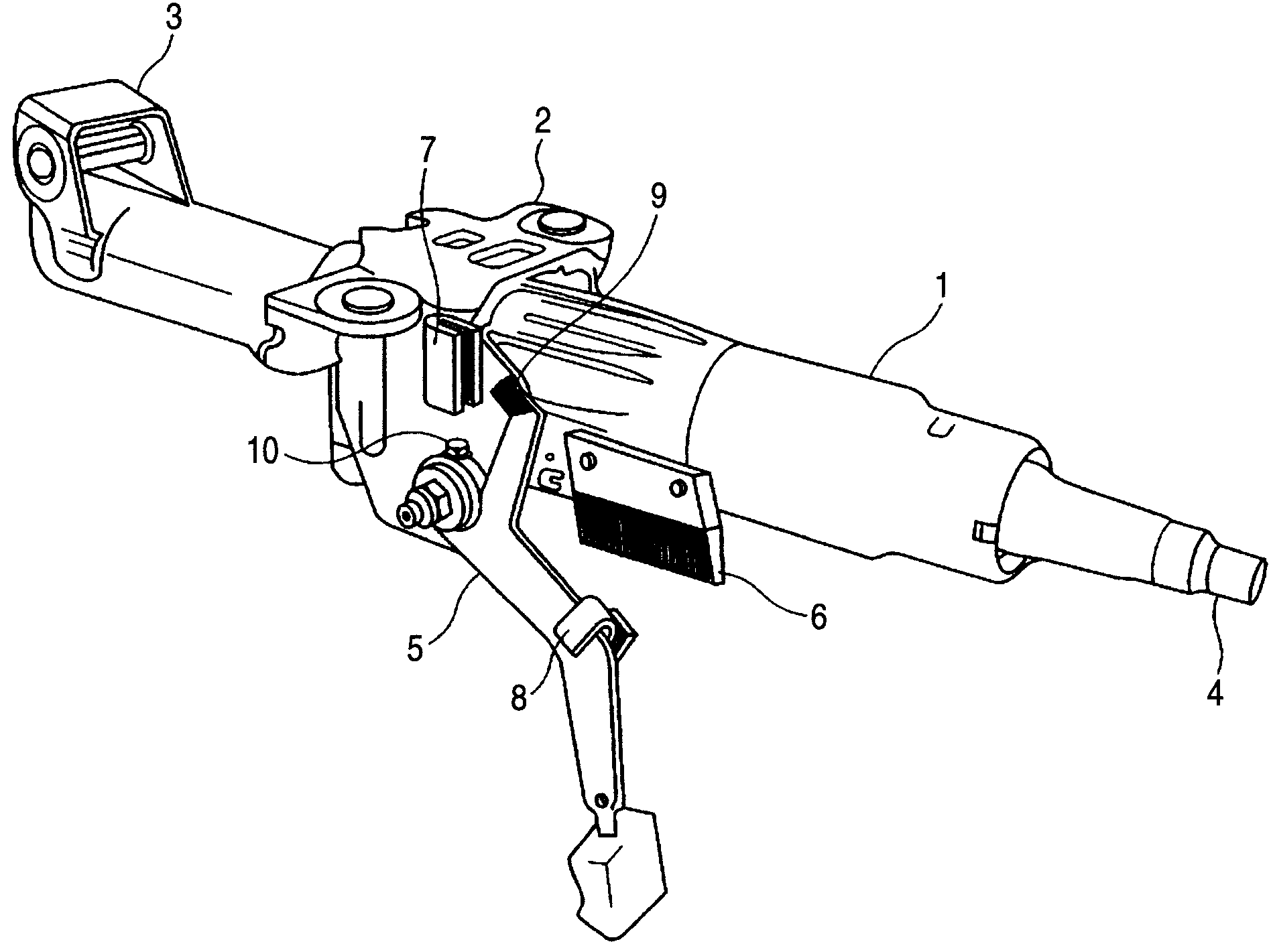
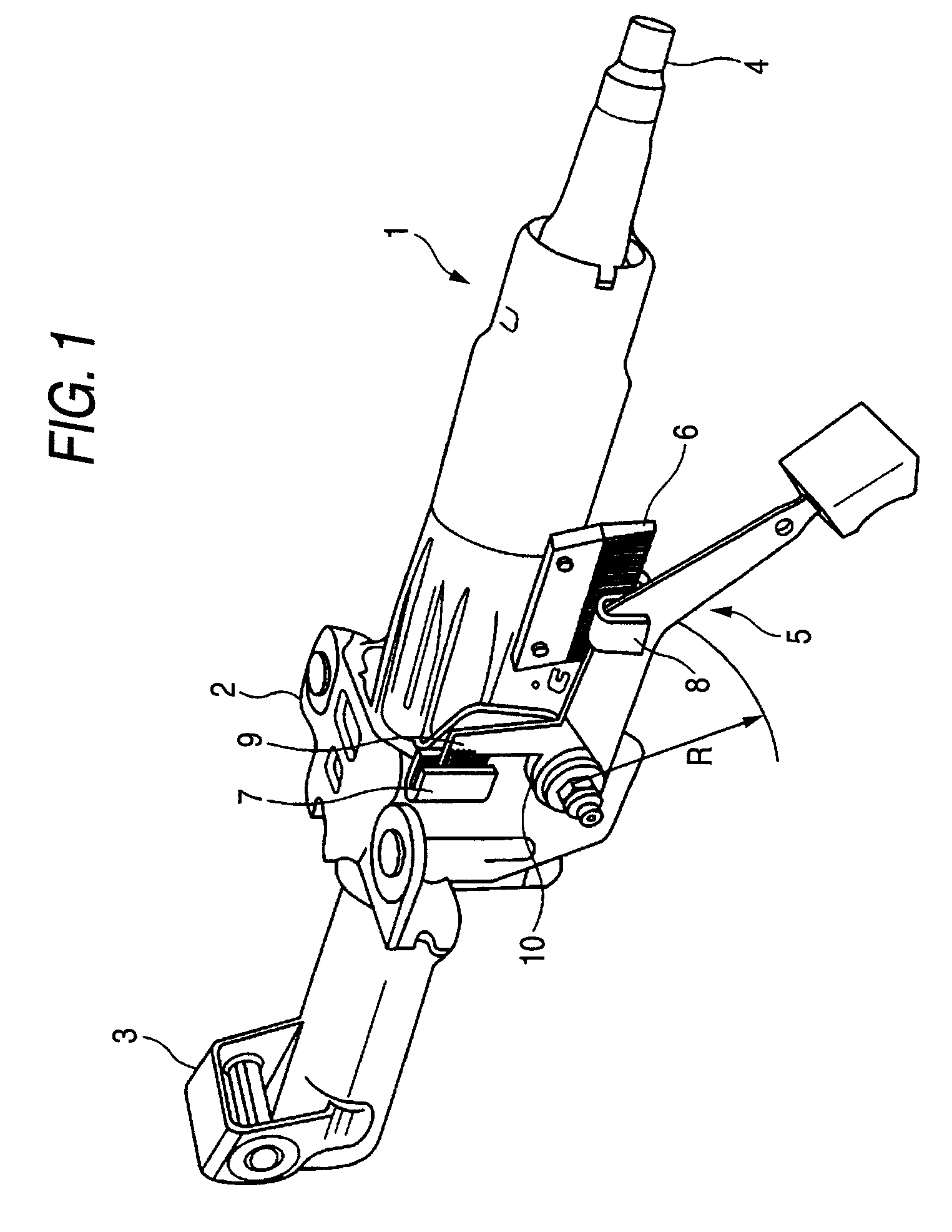
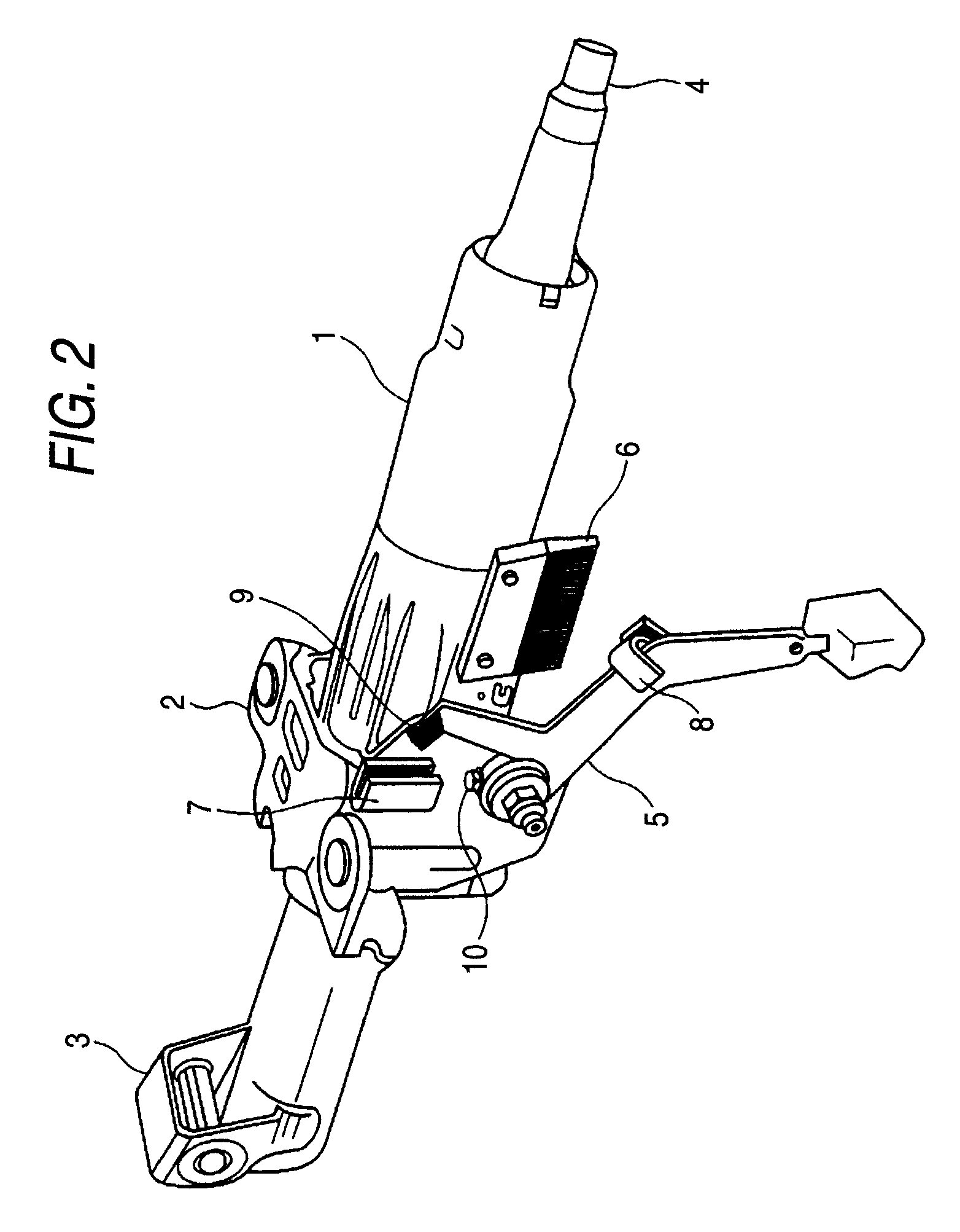
[0073]FIGS. 1 and 2 are perspective views of a steering column apparatus according to a first embodiment of the invention, in which FIG. 1 shows a locked state and FIG. 2 shows an unlocked state.

[0074]A cylindrical column body 1 is attached to a vehicle body (not shown) through brackets 2 and 3. Into the column body 1, a steering shaft 4 for coupling a steering wheel and a steering mechanism (which are not shown) is inserted, and supported rotatably by a not-shown bearing.

[0075]To a side portion of the column body 1, a plate-shaped telescopic gear base 6 is fixed, while a plate-shaped tilt gear base 7 is fixed to the bracket 2. The telescopic gear base 6 has a length corresponding to an adjustment width in the telescopic direction of the column body 1. Further, the tilt gear base 7 has a length corresponding to an adjustment width in the tilt direction of the column body 1. The column body 1 has a long hole for telescopic slide.

[0076]To a rotatable shaft 5a which penetrates into a l...

second embodiment

[0110]Next, a second embodiment of the invention will be described with reference to FIGS. 19 and 20. A tilt / telescopic steering column apparatus according to the second embodiment is characterized in that a tooth trace is inclined so that a contact ratio η increases by force applied in the crash time. Members in the second embodiment similar to those in the above first embodiment are denoted by the same reference signs, and their detailed description is omitted.

[0111]FIG. 19 is a diagram showing a telescopic gear base 6 and a telescopic gear member 8 in the ordinary time. FIG. 20 is a diagram showing the telescopic gear base 6 and the telescopic gear member 8 in the crash time.

[0112]FIG. 19A and FIG. 20A are diagrams, viewed from the vehicle body side, respectively, FIG. 19B is a diagram viewed in the direction of an arrow XIX B in FIG. 19A, FIG. 20B is a diagram viewed in the direction of an arrow XX B in FIG. 20A, FIG. 19C is a diagram viewed in the direction of an arrow XIX C in...

third embodiment

[0117]When an excessive force acts on a column at the crash time of a vehicle, similarly to the case in the above second embodiment, there is fear that gears loosen. When looseness of the gears is produced, a contact ratio of gears lowers, so that there is a possibility that the gears are damaged or intermeshing between the gears itself is released. In order to suppress the above looseness of the gears, it is thought that a member having high rigidity is used in a steering column apparatus or a special mechanism for suppressing the looseness of the gears is used. However, this is not desirable because cost increases and the structure become complicated.

[0118]Therefore, in case that the shape and the size of the gear are set as described below in order to solve the above problem, the problem that the gears are loosened is solved by friction force acting on a tooth surface of the gear. Further, according to the third embodiment of the invention, a steering column apparatus which has s...


PUM


Abstract

When a telescopic gear base 6 and a telescopic gear member 8 are relatively brought close to each other, although their centers shift from each other, even when a tooth tip of a tooth (first tooth) 6a on one surface and a tooth tip of a tooth (second tooth) 8a on one surface contact with each other (at C-point in FIG. 5(b)), the telescopic gear base 6 and the telescopic gear member 8 can continue the relative movement in direction of an arrow (FIG. 5(b)) from such the state, because they contact with each other and intermeshed so that each angle with their tooth continuing directions is set larger than 0° and smaller than 90°. Therefore, since the telescopic gear base 6 and the telescopic gear member 8 intermesh gradually to slide, the tooth 6a and the tooth 8s readily intermesh during slide (at D-point in FIG. 5(c)).

Description

TECHNICAL FIELD[0001]The present invention relates to a steering column apparatus which supports a steering shaft adjustably in at least one direction of a tilt direction and a telescopic direction.BACKGROUND ART[0002]A steering column apparatus is an important safety-maintaining part of a vehicle. In order to secure safety of a passenger in the crash time, how to control the motion of the steering column apparatus in the crash time is very important. Generally, the steering column apparatus itself is provided with an impact energy absorbing mechanism, and also performs an important part as a support member of an air bag housed in a steering wheel.[0003]Further, in order to make a drive posture of a driver most appropriate, a general steering column apparatus, in accordance with driver's physical build and drive posture, can adjust an inclined angle of a steering wheel and can adjust a position in an axial direction of the steering wheel. Accordingly, the steering column apparatus m...

Claims


Application Information

Patent Timeline
Patent Type & Authority Patents(United States)
IPC IPC(8): B62D1/18
CPCB62D1/184
Inventor OKADA, SHINJISHIBAZAKI, HIROSHI
Owner NSK LTD
Why Eureka
Try Eureka