Method for removing a half turn of a coil from a slot of a dynamoelectric machine

a technology of dynamoelectric machines and half turns, which is applied in the field of dynamoelectric machines, can solve the problems of large extraction force required to remove a failed stator half coil, difficult to machine copper, and waste of time, and achieve the effect of facilitating the removal and recycling of coils and reducing the amount of tim

Active Publication Date: 2010-10-26
SIEMENS ENERGY INC
View PDF5 Cites 7 Cited by
  • Summary
  • Abstract
  • Description
  • Claims
  • Application Information

AI Technical Summary

Benefits of technology

[0010]The method of this invention then uses an extraction tool to grip the upended end of the coil, preferably gripping substantially each individual strand of the coil. The extraction tool preferably includes a support fixture having a hydraulic cylinder and piston rod coupled at the cylinder to the support fixture with the piston rod extending vertically upward. A tension plate is mounted to the peripheral end of the piston rod with a ball and socket connection. A clamp for clamping the coil is coupled to the tension plate through clamping fingers that are coupled at one end to either side of the tension plate through ball and socket mountings. The clamping fingers extend from either side of the tension plate to the bottom of the fixture where they support elongated gripping plates extending perpendicular to the fingers. The ball and socket connection coupling the tension plate to the piston rod and the clamping fingers to the tension plate enable the gripping plates to move angularly as the coil is raised from the slot. Preferably, each of the opposing fingers is actuated by a separate hydraulic cylinder which presses the plates toward each other to firmly grip the coil. The method of this invention places the gripping plates over the sides of the coil and actuates the hydraulic cylinders that press the gripping plates towards each other and firmly grip the coil strands; then the piston rod connected to the tension plate is raised to extract the segment of the coil from the slot. The clamping plates are then opened, the piston rod attached to the tension plate is then lowered and the fixture is moved along the slot to then grip the next segment which was just raised from the slot. The process is then repeated until the entire half coil is out of the slot. Preferably the opposing faces of the gripping plates have pyramidically shaped teeth that substantially grip each of the strands of the coil. In the process of step-wise coil extraction the extraction tool exerts such large forces in bending each successive segment radially inward and up and out of the slot that this action creates tremendous interlaminar shear forces. These forces are large enough to essentially separate all or nearly all the individual coil roebelled strands, one from the other, which facilitates removal and recycling of the coil.

Problems solved by technology

One of the advantages of this process is that all the coils and bracing is installed “dry” so the handling of wet and messy epoxies is not required, which saves a considerable amount of time.
One disadvantage associated with the global vacuum impregnated process is the large extraction force required to remove a failed stator half coil.
In addition, copper is also somewhat difficult to machine due to its tendency to plug up the cutting tools.
Tapping copper is very difficult, and adequate lubrication on the tap must be used and the chips must be removed from the tap.
This is done to avoid gumming up the tap to the point it becomes stuck in the copper, which can result in a broken tap.

Method used


Image

  • Method for removing a half turn of a coil from a slot of a dynamoelectric machine
  • Method for removing a half turn of a coil from a slot of a dynamoelectric machine
  • Method for removing a half turn of a coil from a slot of a dynamoelectric machine

Examples


Embodiment Construction

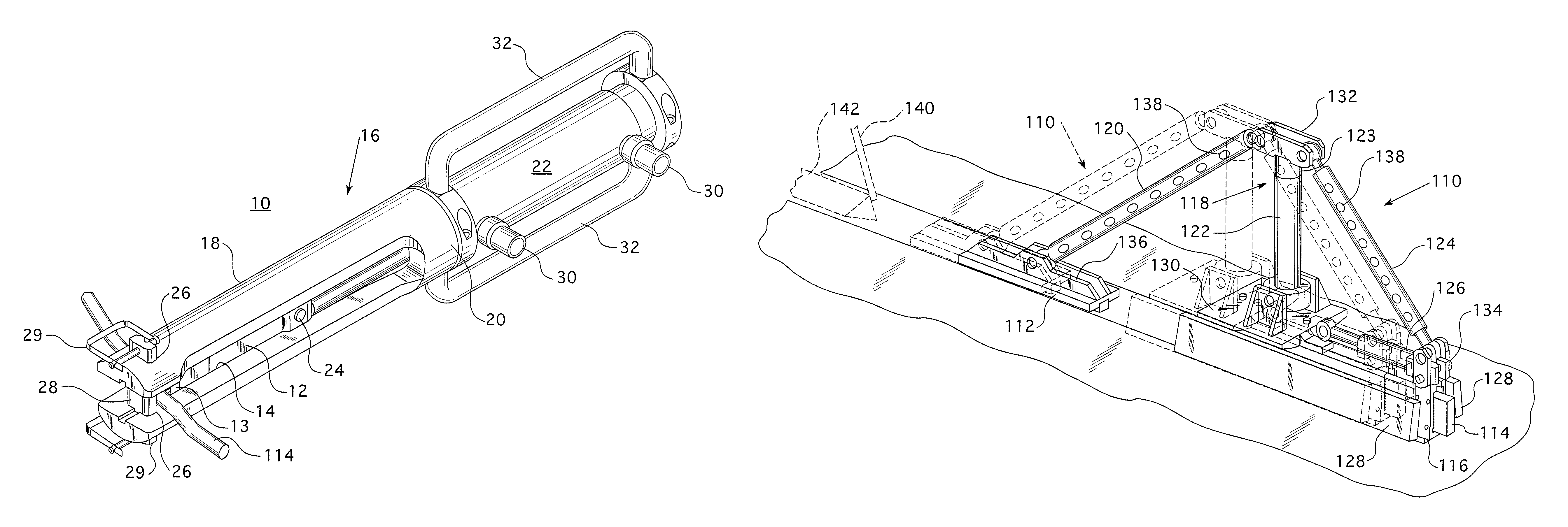
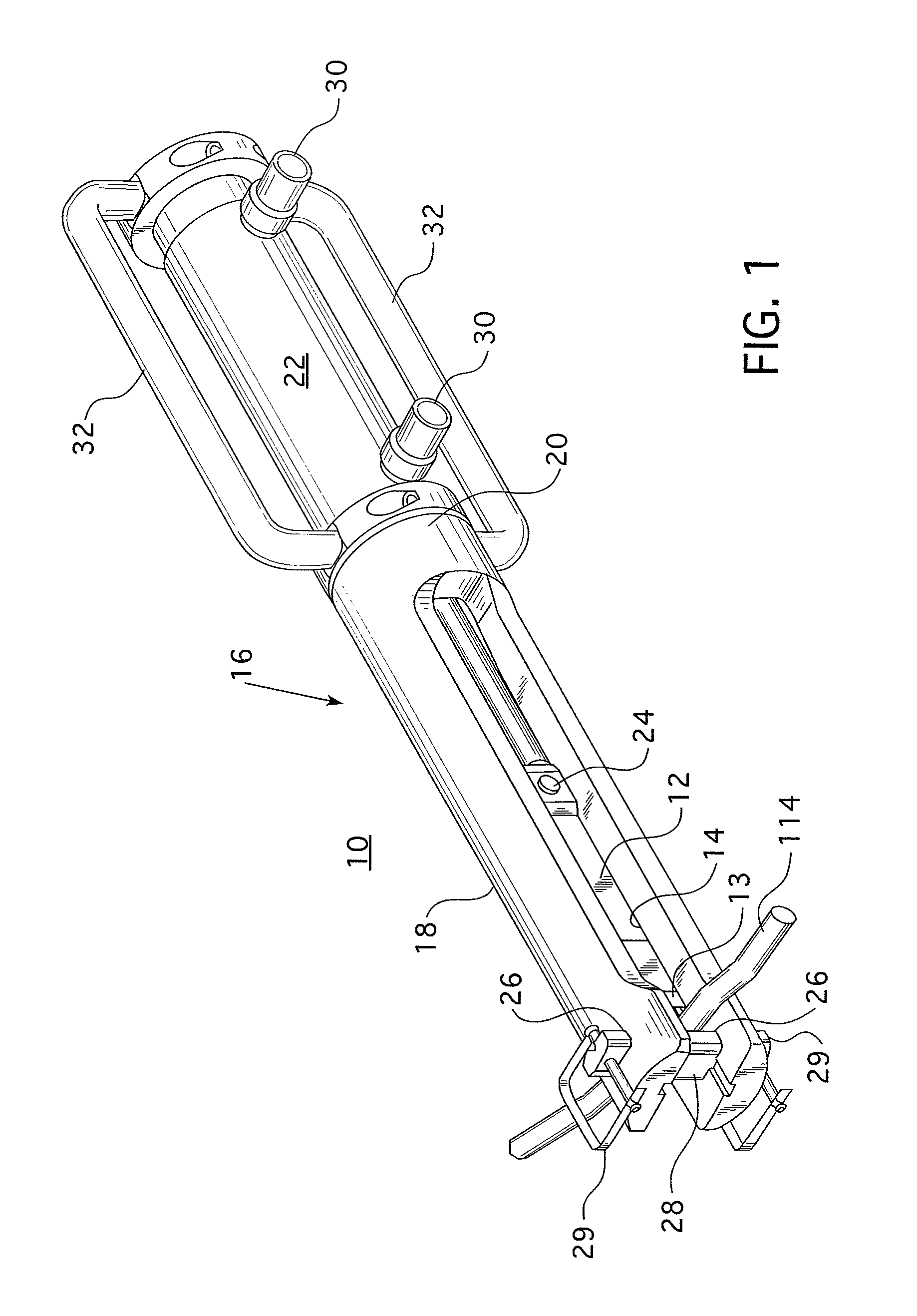
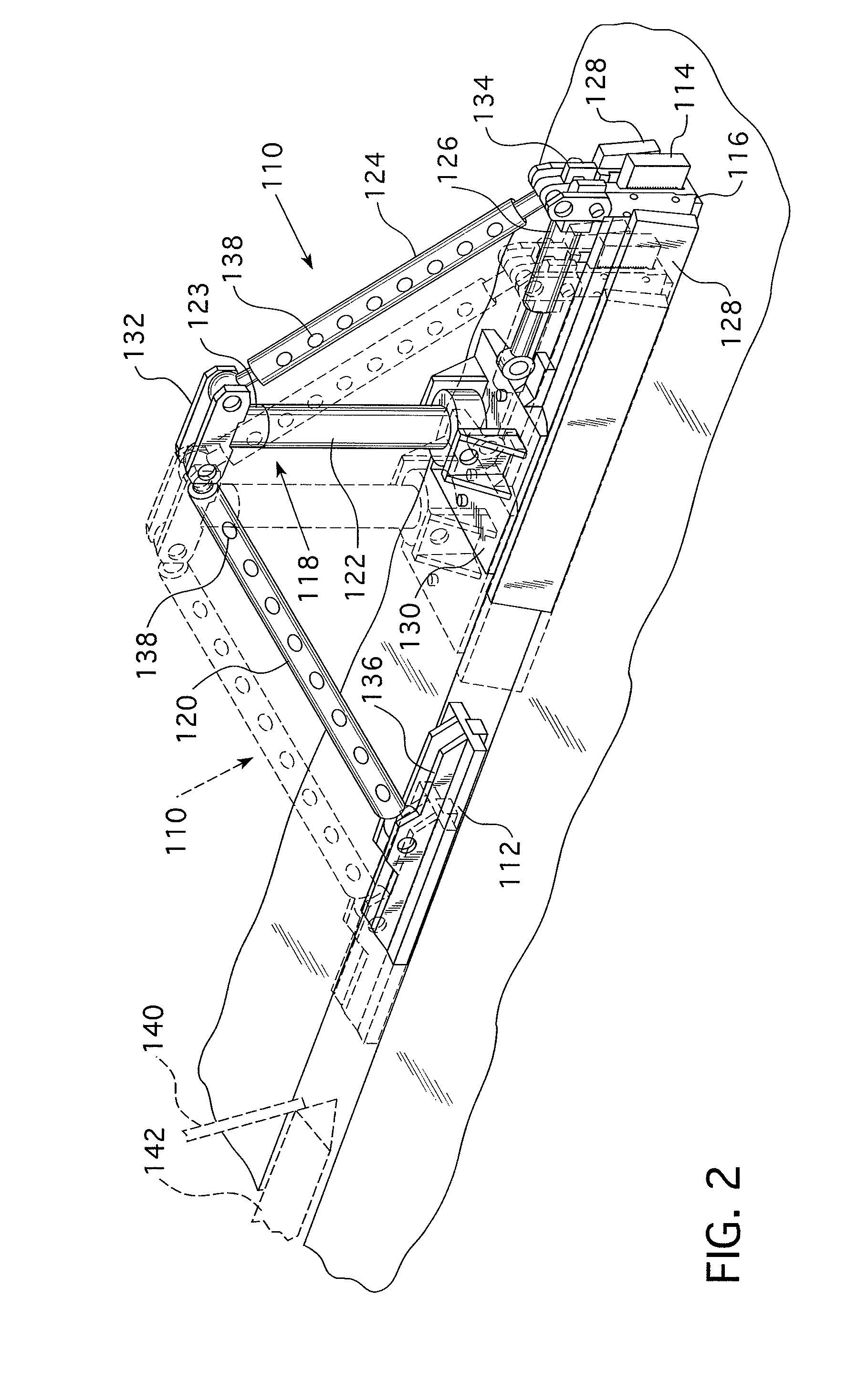
[0016]The improved method of this invention quickly clamps onto the copper strand bundle of a half coil that has been cut in the end-turn region and rips it out of the slot one axial position at a time. As the copper bundle is ripped from the stator slot, the tooling moves along the slot and repeats the process from one end of the slot to the other.

[0017]Directional phrases used herein, such as, for example, upper, lower, top, bottom, left, right, and derivatives thereof for the most part relate to the orientation of the elements shown in the drawings and are not meant to be limiting upon the claims, unless expressly recited therein. As employed herein, the statement that two or more parts are “coupled” together shall mean that the parts are joined together, either directly or joined through one or more intermediate parts. In addition, as employed herein the term “number” shall refer to one and more than one, i.e., a plurality.

[0018]The equipment to remove globally impregnated stato...


PUM

PropertyMeasurementUnit
timeaaaaaaaaaa
rotationaaaaaaaaaa
thickaaaaaaaaaa

Abstract

A method and apparatus which quickly clamps onto the copper strand bundle in the slot of a dynamoelectric machine and rips out the coil from the slot one axial position at a time. As the copper bundle is ripped from the slot the tooling moves along the slot from one end to the other.

Description

BACKGROUND OF THE INVENTION[0001]1. Field of the Invention[0002]This invention pertains generally to dynamoelectric machines, and more particularly to a method and apparatus for removing a resin impregnated coil from a core slot of such a machine.[0003]2. Related Art[0004]A process for globally vacuum impregnating entire large electric generated stator cores was developed by the Siemens Corporation in Germany approximately ten years ago. The process involves a large vacuum tank capable of holding the entire wound stator core as well as space for power rollers to rotate the core while it is partially submerged in liquid resin in the vacuum tank. A significant number of large electric generators have been manufactured using this process since it was introduced. One of the advantages of this process is that all the coils and bracing is installed “dry” so the handling of wet and messy epoxies is not required, which saves a considerable amount of time. Secondly, the liquid resin under th...

Claims


Application Information

Patent Timeline
Patent Type & Authority Patents(United States)
IPC IPC(8): H02K15/10
CPCB23P19/04H02K15/0006Y10T29/49009Y10T29/49071Y10T29/49815Y10T29/53274Y10T29/53152Y10T29/53143
Inventor DAILEY, GEORGE FMCDONALD, ERIC SSTEIN, ADAMVINDLER, MICHAELORNDOFF, JAREDFAYEWICZ, RYANJURGEN, JASON V
Owner SIEMENS ENERGY INC
Why Eureka
Try Eureka