Downhole safety valve apparatus and method

a safety valve and downhole technology, applied in the direction of wellbore/well accessories, fluid removal, sealing/packing, etc., can solve the problems of invasive installation after production tubing placement in the wellbore, high cost and time-consuming, and catastrophic blowout of production and other fluids into the atmospher

Active Publication Date: 2010-11-02
BAKER HUGHES INC
View PDF37 Cites 39 Cited by
  • Summary
  • Abstract
  • Description
  • Claims
  • Application Information

AI Technical Summary

Problems solved by technology

Absent safety valves, sudden increases in downhole pressure can lead to catastrophic blowouts of production and other fluids into the atmosphere.
Furthermore, because former systems were run with the production tubing, installations after the placement of production tubing in the wellbore are invasive.
This process is expensive and time consuming, so it is typically performed on wells having enough long-term production capability to justify the expense.

Method used


Image

  • Downhole safety valve apparatus and method
  • Downhole safety valve apparatus and method
  • Downhole safety valve apparatus and method

Examples


Embodiment Construction

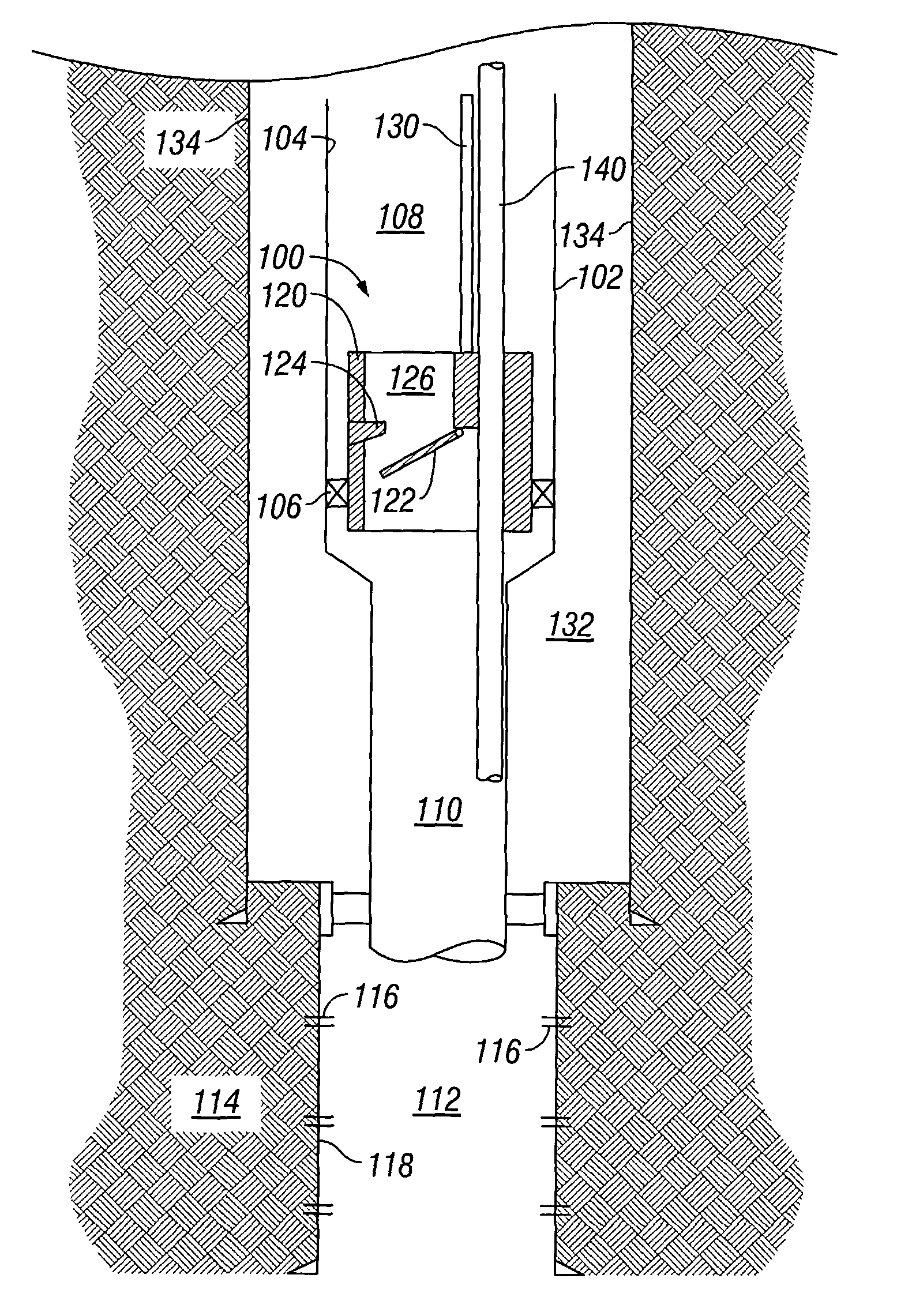
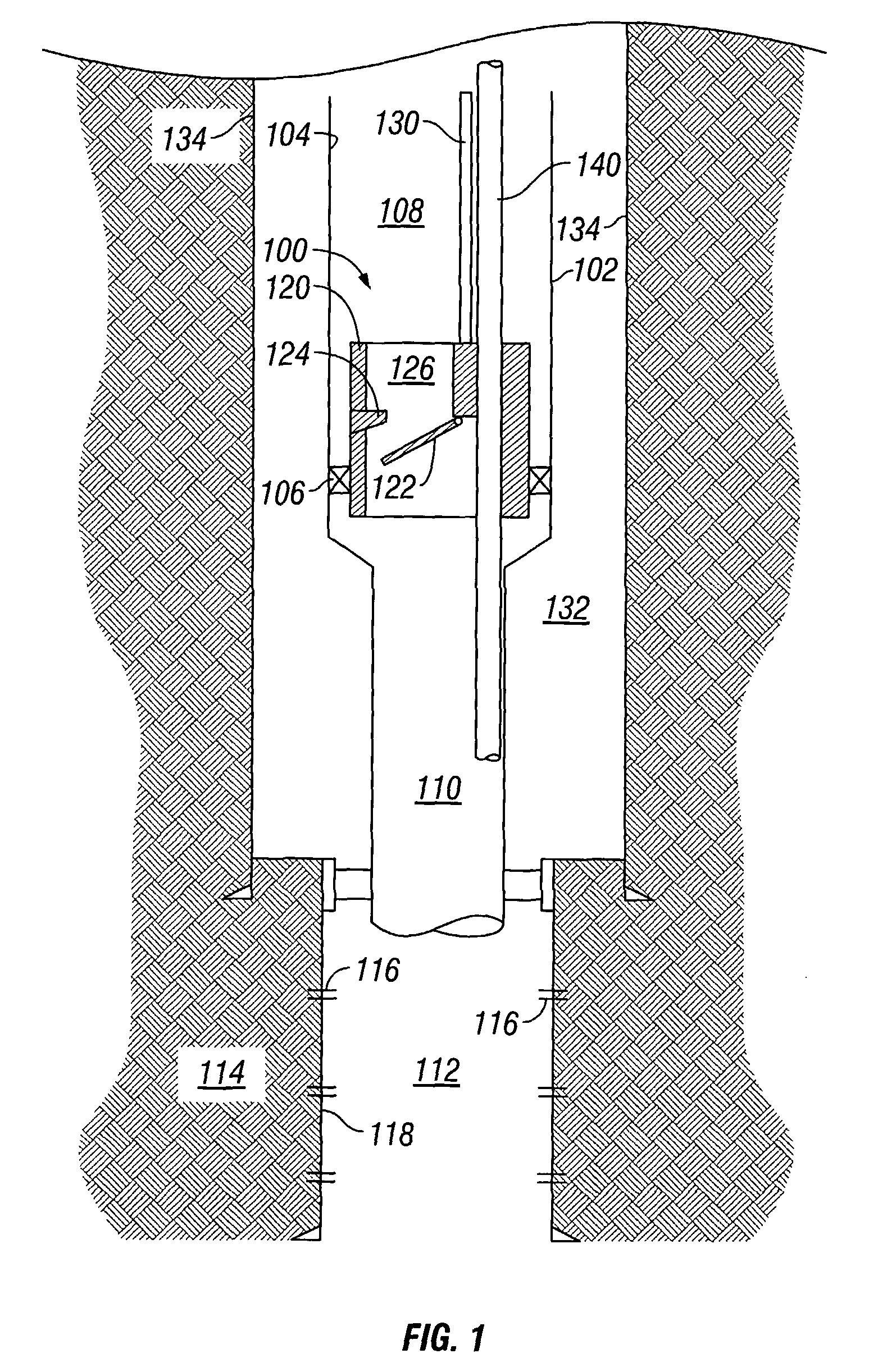
[0024]Referring initially to FIG. 1, a safety valve assembly 100 is shown schematically deployed in a string of production tubing 102. Safety valve assembly 100 can be of any valve type known to one of ordinary skill in the art and may be deployed integrally within tubing string 102 or may be held within a bore 104 of tubing 102 and isolated with a hydraulic seal 106. Nevertheless, the safety valve assembly 100 functions to selectively isolate a first zone 108 of tubing 102 from a second zone 110 of tubing 102. Typically, zone 108 is in communication with a surface location (not shown) at the uppermost end of tubing 102 and zone 110 is in communication with one or more production zones 112. To communicate production fluids from the subsurface formation 114 to the surface, production fluids flow through perforations 116 in a production casing or wellbore 118, up through lower zone 110 of production tubing 102, past safety valve 100, through upper zone 108 of tubing 102 and to the sur...


PUM


Abstract

The application discloses a valve, which may include either a safety valve or a storm surge choke valve or the like, to isolate a zone below a valve from a string of production tubing. Preferably, the valve includes a flow interruption surface assembly, such as a flapper valve or a ball valve, displaced by an operating conduit extending from a surface location to the valve through the inside of the production tubing. The application also discloses a bypass-conduit inside the production tubing to allow communication from a surface location to the production zone when the valve is in either an open or a closed location.

Description

CROSS-REFERENCE TO RELATED APPLICATION[0001]This application claims the benefit of provisional application U.S. Ser. No. 60 / 522,498 filed Oct. 7, 2004.BACKGROUND OF THE INVENTION[0002]The present invention generally relates to subsurface valves. More particularly, the present invention relates to an apparatus and method to operate a subsurface valve with a capillary tube extending from a surface station. More particularly still, the present invention relates to an apparatus and method to operate a subsurface valve with a capillary tube extending from a surface station from within the tubing string upon which the valve is mounted. The valve may be a safety valve, a storm check valve, or a choke valve. The flow interrupting device or valve may be formed from a flapper, a ball valve, or a gate valve or any other type of flow diverting valve assembly which may be actuated from the surface.[0003]Subsurface valves are typically installed in strings of tubing deployed to subterranean wellb...

Claims


Application Information

Patent Timeline
Patent Type & Authority Patents(United States)
IPC IPC(8): E21B34/10
CPCE21B34/105E21B43/25
Inventor BOLDING, JEFFREY L.SMITH, DAVID RANDOLPH
Owner BAKER HUGHES INC
Why Eureka
Try Eureka