Electrical depilator

a technology of electric depilators and depilators, which is applied in the field of electric depilators, can solve the problems of high manufacturing cost, difficult die sinking, and troublesome assembly procedure, and achieve the effects of reducing the number of members, reducing the difficulty of die sinking, and quick depilation of hairs

Inactive Publication Date: 2010-11-02
LIU LAISHENG
View PDF58 Cites 3 Cited by
  • Summary
  • Abstract
  • Description
  • Claims
  • Application Information

AI Technical Summary

Benefits of technology

[0008]In view of the above disadvantages in the conventional art, it is an object of the present invention to provide an electrical depilator which is easy in die sinking, convenient in assembling, and of low cost.
[0016]With the above structure, when energized, the driving wheel of the motor drives the whole set of singe-pieces through the reduction gear set to rotate around the arcuate shaft. Thereby, the single-pieces on the gradually-narrowed side of the arcuate shaft are caused to perform a clipping action, and those on the gradually-widened side of the arcuate shaft perform a loosening action. Thus, hairs are depilated quickly on the gradually-narrowed side of the arcuate shaft directly by use of the clipping surfaces of the singe-pieces, so as to depilate hairs quickly.
[0017]The electrical depilator according to the present invention has the following advantages over the prior arts. The depilator only has a plurality of single-pieces. That is, the two types of pieces in the conventional art, i.e. the base pieces performing pressure transfer and motion functions and the thin clipping pieces supported by the pieces and performing a hair clipping function, are simplified as one type of single-pieces. As a result, the thin clipping pieces are eliminated. Thus, the number of members is reduced, which facilitates the die sinking because only the die for forming single-pieces is needed. In addition, the structure is greatly simplified and only the single-pieces are required to be assembled in assembling. Therefore, the assembling procedure is easy and the cost is reduced.

Problems solved by technology

Therefore, it is difficult in die sinking.
Furthermore, the cost of manufacture is high because the structure of the depilator is complicated and the thin clipping pieces 6′ are generally made of metals.
Moreover, the assembling procedure is very troublesome because of the alternate arrangement in the form of one base piece 5′→two thin clipping pieces 6′→one base piece 5′ .

Method used


Image

  • Electrical depilator
  • Electrical depilator
  • Electrical depilator

Examples


Embodiment Construction

[0034]Embodiments of the present invention will be described in detail with reference to attached drawings.

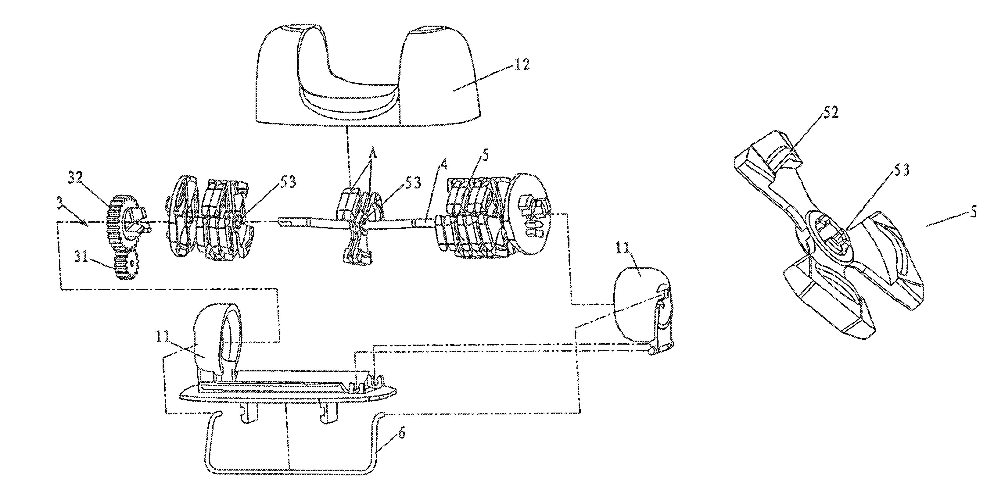
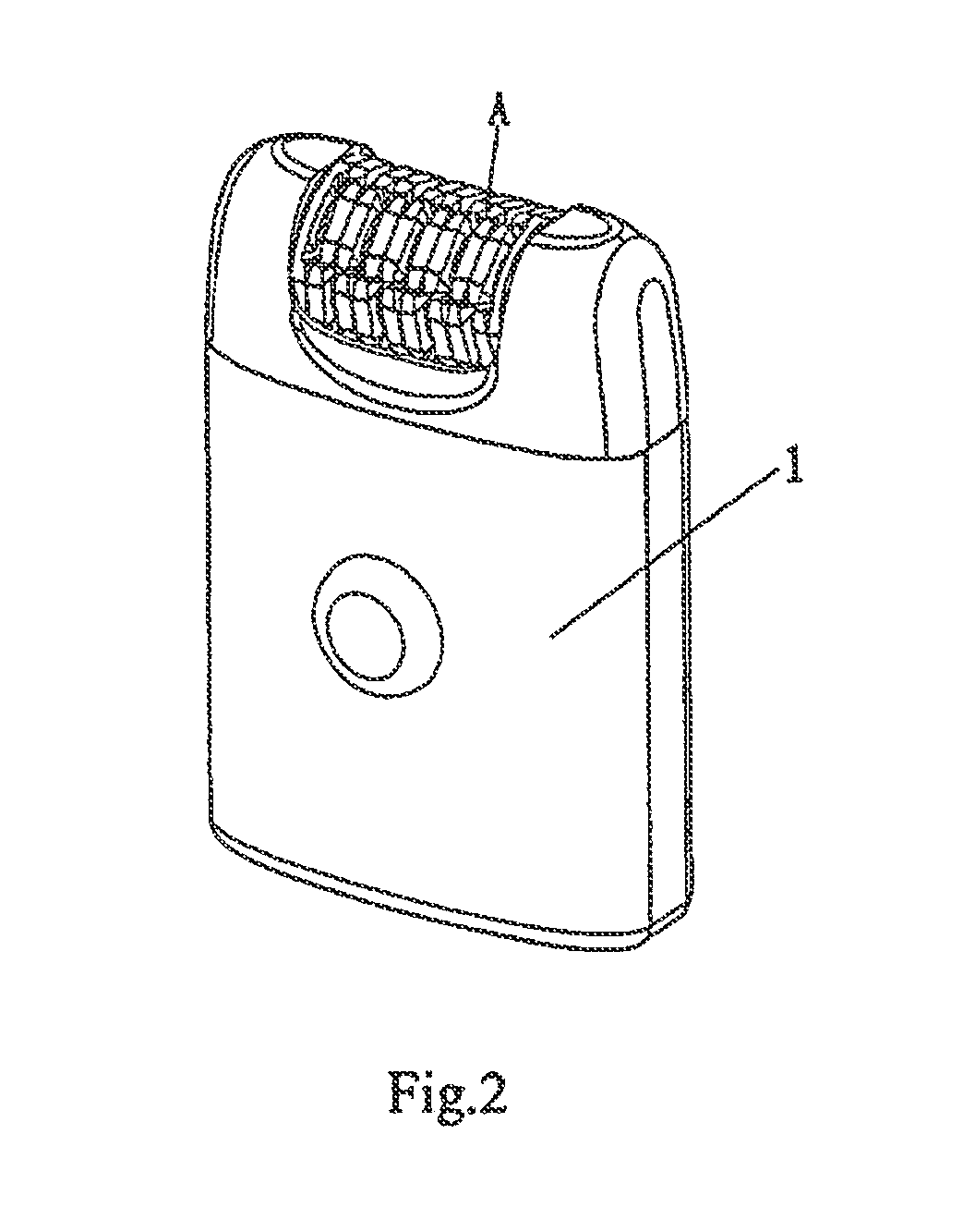
[0035]As shown in FIG. 2 in conjunction with FIG. 3, an electrical depilator according to one preferred embodiment of the present invention comprises a main body 1, a motor (not shown), a reduction gear set 3, an arcuate shaft 4 and a set of single-pieces 5.

[0036]The arcuate shaft 4 is supported on a shaft seat 11 of the main body 1.

[0037]A first stage gear 31 of the reduction gear set 3 meshes with the driving wheel (not shown) of the motor, and a last stage gear 32 is fixed on the single-piece 5 which is located at the endmost position.

[0038]Each single-piece 5 has a clipping surface 51 and a supporting portion 52, as shown in FIGS. 4-8. The whole set of single-pieces 5 are arranged in such a manner that the clipping surfaces 51 are opposite to each other. A clipping gap A is formed between the opposite surfaces 51 of two single-pieces 5, as shown in FIGS. 2 and 3. The whole ...


PUM


Abstract

The present invention provides an electrical depilator comprising substantially of a main body, a motor, a reduction gear set, an arcuate shaft and a set of single-pieces. The arcuate shaft is supported on a shaft seat of the main body. A first stage gear of the reduction gear set meshes with the driving wheel of the motor, and a last stage gear is fixed on the single-piece which is located at the endmost portion. Each single-piece has a clipping surface and a supporting portion. The whole set of single-pieces are arranged in a manner that the clipping surfaces are opposite to each other. A clipping gap is formed between opposite surfaces of two single-pieces. The whole set of single-pieces are coupled together by fixing members so as to rotate synchronously. The whole set of single-pieces are fitted over the arcuate shaft all together. The electrical depilator is easy in die sinking, convenient in assembling, and of low cost.

Description

BACKGROUND OF THE INVENTION[0001]1. Field of the Invention[0002]The present invention relates to an electrical depilator, in particularly, to an electrical depilator which is easy in die sinking, convenient in assembling, and of low cost.[0003]2. Description of the Related Art[0004]There are various electrical depilators with different constructions in conventional technology and there are a great many patents relating to depilators. FIG. 1 shows a type of depilator among conventional ones. The depilator comprises a main body 1′, a motor 2′, a reduction gear set 3′, an arcuate shaft 4′, a set of base pieces 5′ and thin clipping pieces 6′. Each clipping piece 6′ is fixed on a corresponding base piece 5′, that is, the thin clipping piece 6′ is supported on and driven by the base piece 5′ to move correspondingly. The whole set of base pieces 5′ are coupled together by shifting yokes (not shown, or by bearing housings or shaft pins) so as to rotate synchronously. The whole set of base p...

Claims


Application Information

Patent Timeline
Patent Type & Authority Patents(United States)
IPC IPC(8): A61B17/50
CPCA45D26/0028
Inventor LIU, LAISHENG
Owner LIU LAISHENG
Why Eureka
Try Eureka