
Magnetic device and frequency detector

a frequency detector and magnetic device technology, applied in the direction of magnets, magnet bodies, instruments, etc., can solve the problems of not knowing the half-value width of the output dc voltage peak and the half-value width of the peak of the output dc voltage, and achieve the effect of small half-value width of the peak

Inactive Publication Date: 2010-11-02
TDK CORPARATION
View PDF0 Cites 11 Cited by
  • Summary
  • Abstract
  • Description
  • Claims
  • Application Information

AI Technical Summary

Benefits of technology

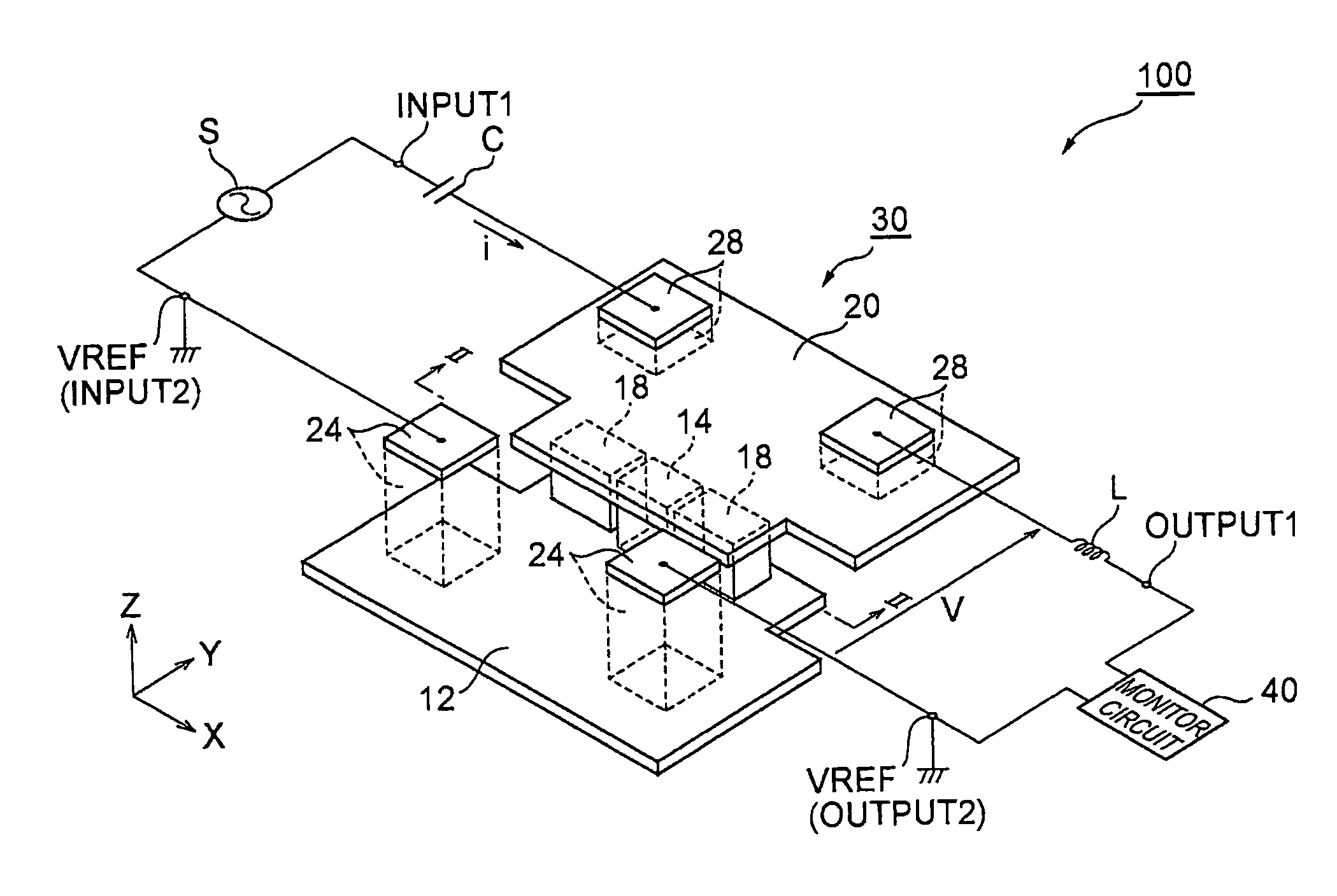
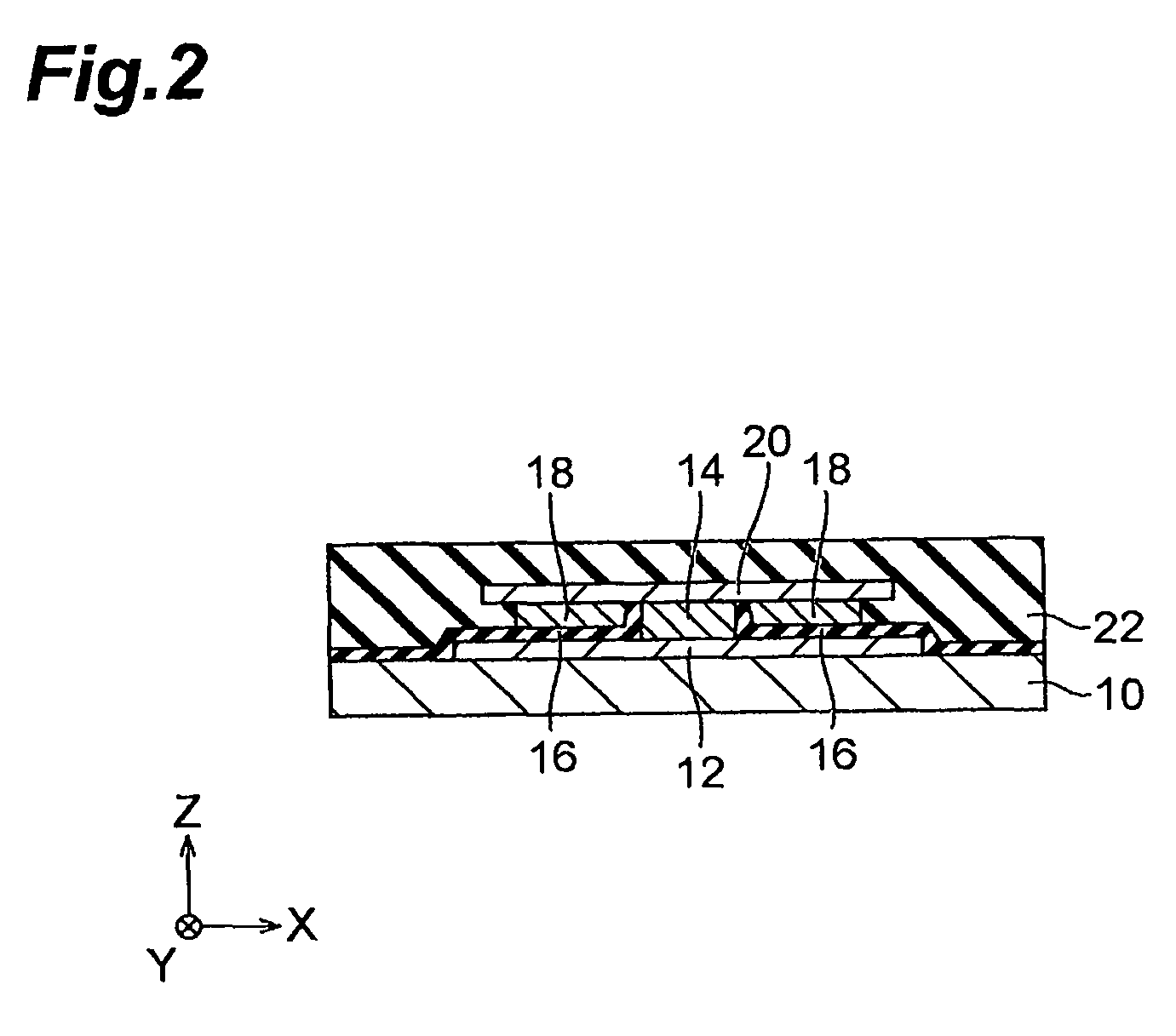
[0013]This makes it possible to apply a predetermined magnitude of magnetic field to the magnetization free layer. Then, the natural frequency (resonance frequency) of the magnetization direction of the magnetization free layer is determined depending on the magnitude of the magnetic field applied to the magnetization free layer. Accordingly, a magnetic device can be obtained which outputs a DC component by selectively varying the voltage of a signal with a specific frequency corresponding to the component of the determined resonance frequency of the input AC signal.
[0015]This reduces particularly the half-value width of the peak of the output DC voltage of the magnetic device.
[0017]This can increase the output DC voltage of the magnetic device. That is, since the spin polarization ratio of the half metal such as a Heusler alloy at room temperature is approximately 100%, the magnetoresistive effect ratio of the magnetoresistive effect element will increase. For this reason, when the magnetization direction of the magnetization free layer resonates with the AC current flowing through the magnetoresistive effect element, the resistance value of the magnetoresistive effect element will vary more abruptly at this frequency. This results in an increase in the output DC voltage of the magnetic device.
[0022]A frequency detector according to the present invention comprises any of the above-described magnetic devices and a monitor circuit for monitoring the voltage output from the output terminal. According to the present invention, the voltage of a signal with a specific frequency of the input AC signal is detected by the monitor circuit. Accordingly, this device functions as a frequency detector. Furthermore, since the magnetic device having a sufficiently small half-value width of the peak of the output DC voltage as described above is used, a frequency detector with a high frequency resolution can be obtained.

Problems solved by technology

However, in the conventional magnetoresistive effect element exhibiting the spin torque diode effect, the half-value width of the peak of the output DC voltage is not sufficiently small and also the element structure for reducing the half-value width of the peak of the output DC voltage has not been known.

Method used


Image

  • Magnetic device and frequency detector
  • Magnetic device and frequency detector
  • Magnetic device and frequency detector

Examples


example 1

[0106]Hereinafter, in order to clarify the effect of the present invention further, the description is made using examples and a comparative example. FIG. 21 to FIG. 24 are views showing a relationship of the frequency of an input signal vs. the output voltage with regard to magnetic devices concerning Examples 1 to 4. Moreover, FIG. 25 is a view showing a relationship of the frequency of an input signal vs. output voltage of a magnetic device concerning Comparative Example 1.

[0107]For the magnetic devices concerning Examples 1 to 4, the nonmagnetic layer which the magnetoresistive effect element has comprises the insulating layer portion 4b comprising an insulating material and the current-constricting layer portion 4a which passes through the insulating layer portion 4b in its film thickness direction (see FIG. 3, FIG. 5). Moreover, for the magnetic devices concerning Example 1 and Example 2, a ferromagnetic ferromagnetic layer 3A, the upper ferromagnetic layer 3C, and the magneti...


PUM


Abstract

A magnetic device includes: a magnetoresistive effect element having a magnetization fixed layer, a magnetization free layer, and a nonmagnetic layer sandwiched between the magnetization fixed layer and the magnetization free layer; an input terminal for feeding an AC signal to the magnetoresistive effect element in its stacking direction; and an output terminal for extracting an output voltage from the magnetoresistive effect element, wherein the nomagnetic layer includes an insulating layer portion comprising an insulating material, and a current-constricting layer portion comprising a conductive material which passes through the insulating layer portion in its film thickness direction.

Description

BACKGROUND OF THE INVENTION[0001]1. Field of the Invention[0002]The present invention relates to a magnetic device and a frequency detector.[0003]2. Related Background of the Invention[0004]As a magnetoresistive effect element, a GMR (Giant Magnetoresistive) element comprising a nonmagnetic conductive layer interposed between a fixed layer whose magnetization direction is fixed and a magnetization free layer whose magnetization direction varies freely is known. Moreover, as another magnetoresistive effect element, a TMR (Tunnel Magnetoresistive) element comprising a nonmagnetic insulating layer interposed between the fixed layer and the magnetization free layer is known. A current fed through such a magnetoresistive effect element provides a spin-polarized current, which then interacts with a spin accumulated within the magnetization free layer to generate a torque, and as a result the magnetization direction of the magnetization free layer will vary depending on the polarity of the...

Claims


Application Information

Patent Timeline
Patent Type & Authority Patents(United States)
IPC IPC(8): G01R33/02
CPCB82Y25/00G01R33/093H01F10/3259H01L27/22H01L43/08H01F10/3254G01R23/07H01F10/1936H01F10/3272H10B61/00H10N59/00H10N50/10
Inventor KOGA, KEIJIKAKINUMA, YUJIMIYAUCHI, DAISUKE
Owner TDK CORPARATION
Learn More