Centrifugal vibrator vibration damping device

A vibration damping device, vibrator-type technology, applied in inertial effect dampers, springs/shock absorbers, vibration suppression adjustment, etc., can solve the problems of reduced vehicle acceleration performance, increased damper weight and size, etc.

Active Publication Date: 2018-05-25
HONDA MOTOR CO LTD
View PDF1 Cites 0 Cited by
  • Summary
  • Abstract
  • Description
  • Claims
  • Application Information

AI Technical Summary

Problems solved by technology

Therefore, in order to increase the vibration damping torque, it is sufficient to increase the mass and swing radius of the inertial mass body, but if the mass and swing radius of the inertial mass body are increased, the damper itself that is provided with the centrifugal vibrator type vibration damping device will be caused. Increase in weight and size, so there is a problem that the inertial mass of the damper itself increases to degrade the acceleration performance of the vehicle

Method used


Image

  • Centrifugal vibrator vibration damping device
  • Centrifugal vibrator vibration damping device
  • Centrifugal vibrator vibration damping device

Examples


Embodiment Construction

[0024] Below, according to Figure 1 to Figure 7 Embodiments of the present invention will be described.

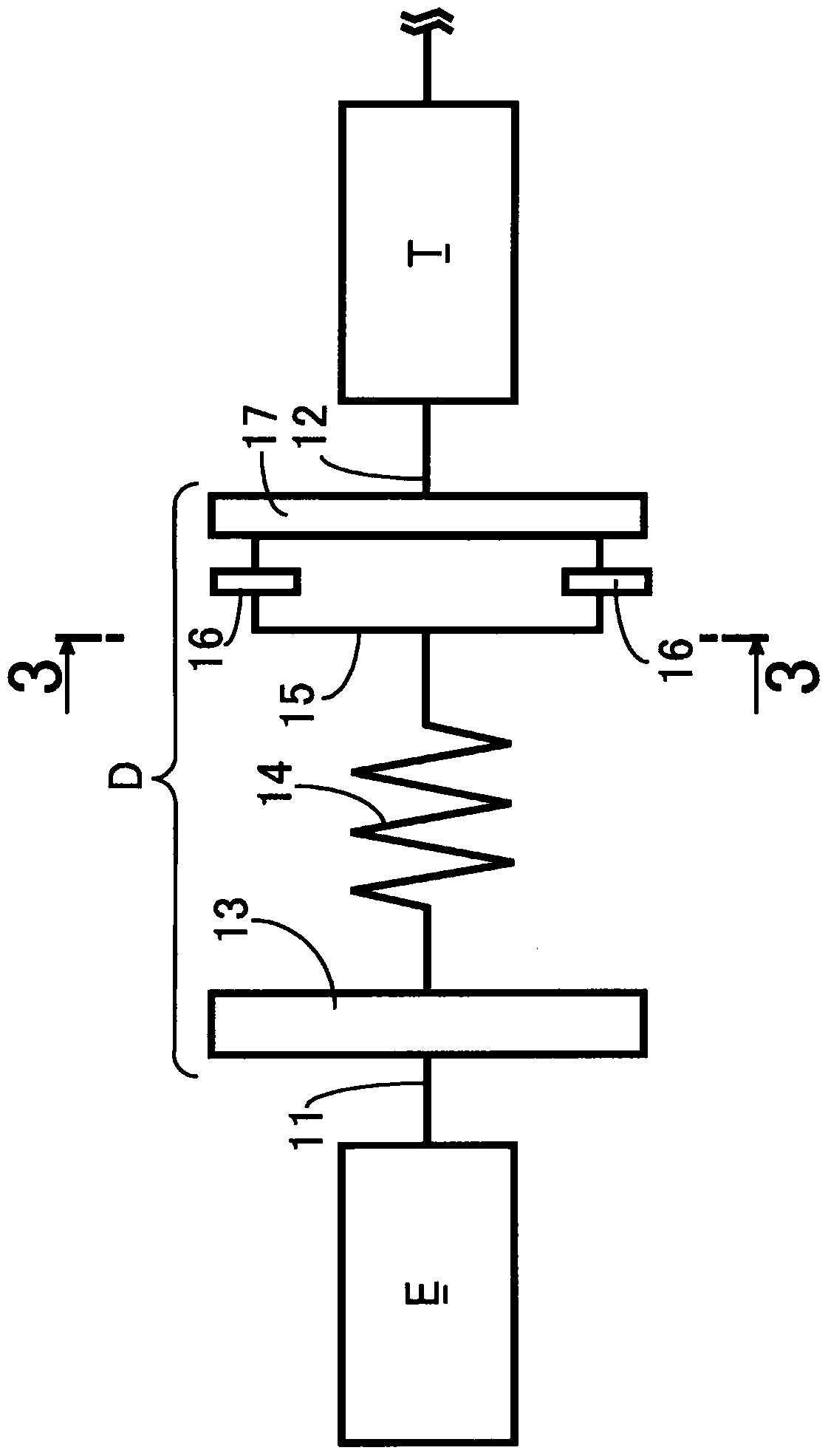
[0025] Such as figure 1 As shown, the damper D is arranged between the crankshaft 11 of the engine E of the automobile and the main shaft 12 of the transmission T. The damper D has: a primary flywheel 13 connected to the crankshaft 11; connected to the The hub portion 15 on the primary flywheel 13; the three first inertial mass bodies 16 connected to the hub portion 15 in a relatively rotatable manner in the circumferential direction; and a secondary flywheel that cooperates with the primary flywheel 13, and The ring-shaped second inertial mass body 17 is connected to the three first inertial mass bodies 16 . . . relatively freely in the circumferential direction.

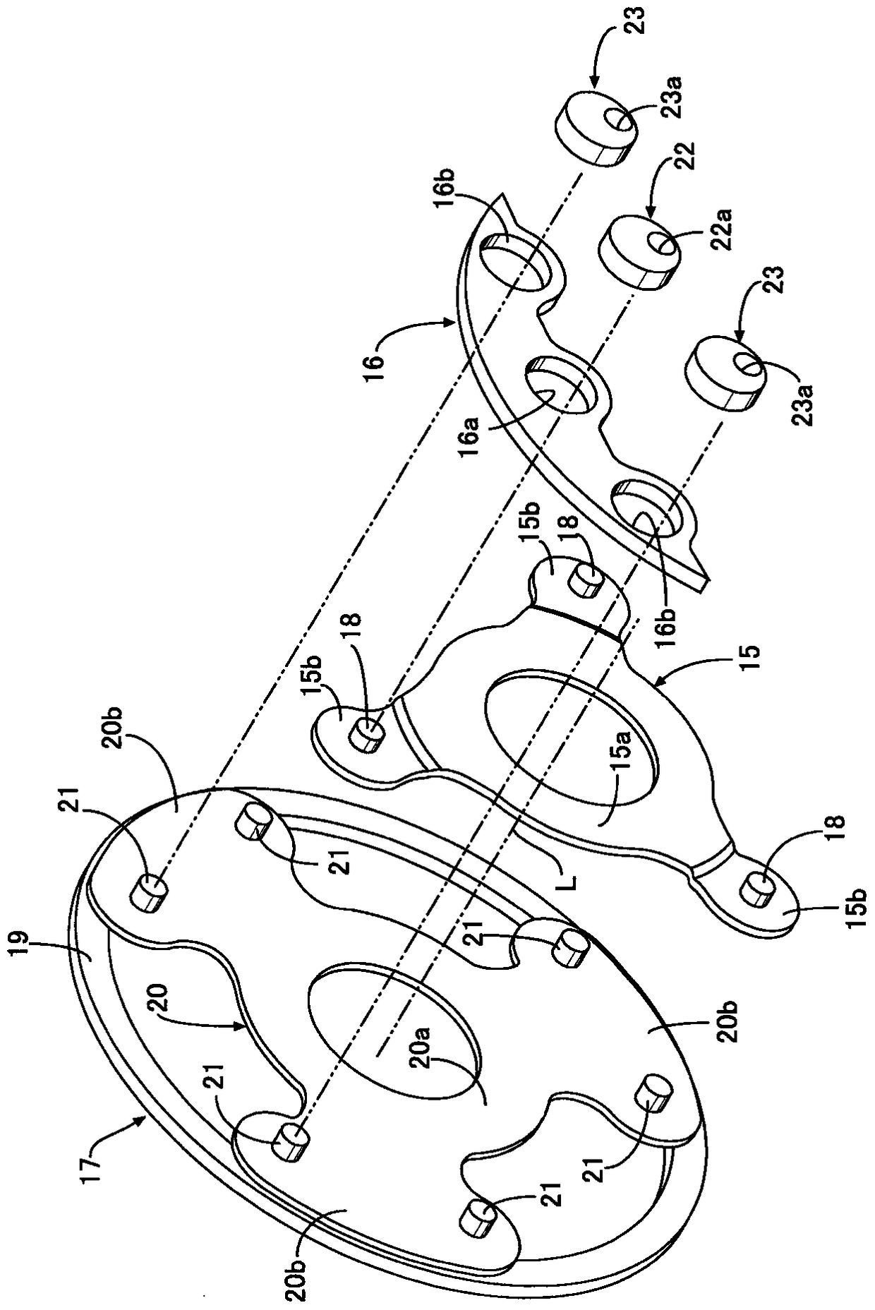
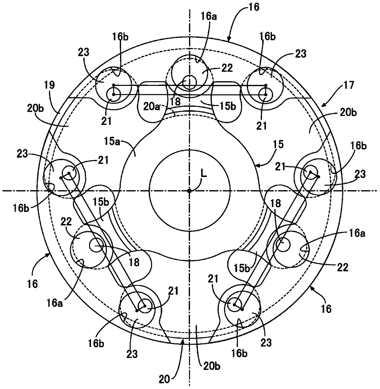
[0026] Such as Figure 2 to Figure 5 As shown, the hub portion 15 is formed by pressing a sheet metal material, and has an annular support portion 15a and three arm portions 15b protruding radially outward ...


PUM


Abstract

A centrifugal pendulum vibration control device for an engine includes an input member, a first link member, a first inertia mass body, a second link member, and a second inertia mass body. The input member is rotated by an engine. The first link member is rotatably connected to the input member. The first inertia mass body is supported on the input member via the first link member so as to perform pendulum motion. The second link member is rotatably connected to the first inertia mass body. The second inertia mass body is supported on the first inertia mass body via the second link member so as to perform pendulum motion. The input member and the second inertia mass body are coaxially disposed so as to be relatively rotatable.

Description

technical field [0001] The present invention relates to a centrifugal vibrator type vibration damping device arranged between an engine and a transmission for reducing vibration generated by rotation fluctuation of the engine. Background technique [0002] Regarding such a centrifugal vibrator type vibration damping device, the following Patent Document 1 has known a structure in which four inertial mass bodies are supported by two arm members on the outer periphery of the support member, and four inertial mass bodies are supported by the support member, the inertial mass bodies, and the The two arm members constitute a four-section parallel link, so that the inertial mass body moves in parallel along an arc-shaped trajectory relative to the supporting member. [0003] prior art literature [0004] patent documents [0005] Patent Document 1: Japanese Patent Laid-Open No. 2012-141018 [0006] In addition, in the centrifugal vibrator type vibration damping device, the magn...

Claims


Application Information

Patent Timeline
Patent Type & Authority Patents(China)
IPC IPC(8): F16F15/14F16F7/10
CPCF16F15/145
Inventor 宫岛俊希
Owner HONDA MOTOR CO LTD
Why Eureka
Try Eureka