Compact achromatic optical interferometer of the three-wave lateral shearing type

a technology of lateral shearing and achromatic optical interferometer, which is applied in the field of analysis of the wavefront of light beam, can solve the problems of difficult implementation, limited measurement of strongly disturbed light beams or light beams with a very large spectrum width, and less robustness

Active Publication Date: 2010-11-02
OFFICE NAT DETUD & DE RECH AEROSPATIALES
View PDF6 Cites 11 Cited by
  • Summary
  • Abstract
  • Description
  • Claims
  • Application Information

AI Technical Summary

Benefits of technology

[0024]In the approach consisting in considering the emerging beams as replicas of the incident beam, the phase function diffracts plural sub-beams including the three main sub-beams and secondary sub-beams. The multiplication by an intensity function makes it possible to minimize the energy being diffracted in the secondary sub-beams so that there essentially remain only the three main sub-beams, useful for the analysis.
[0026]Such a method operates with a polychromatic light and, while adjusting the observation distance, makes it possible, through a continuous setting of the sensitivity and dynamics of the system, to measure highly disturbed light beams.Thus, the user has available a continuous setting flexibility in dynamics for the three-wave lateral shearing type interferometer without the implementing constraints linked to the insertion of the spatial filtering system.

Problems solved by technology

On the other hand, it is complex to be implemented, because of the insertion of the spatial filtering system for selecting the main sub-beams between the grating and the observation plane of the interference fringe system.
Moreover, the spatial filtering system brings limitations for measuring strongly disturbed light beams or light beams with a very large spectrum width.
Estimating the error is also possible by means of such an interferometer, however, it will be less robust in the case of the measurement of high dynamics defect.
In addition, the sampling geometry of wavefronts to be analyzed in the four-wave lateral shearing type interferometer is less optimal than that achieved with a three-wave lateral shearing type interferometer.

Method used


Image

  • Compact achromatic optical interferometer of the three-wave lateral shearing type
  • Compact achromatic optical interferometer of the three-wave lateral shearing type
  • Compact achromatic optical interferometer of the three-wave lateral shearing type

Examples


Embodiment Construction

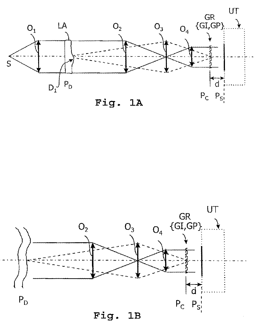
[0044]FIGS. 1A and 1B show two examples of systems for implementing the invention.

[0045]On FIG. 1A, a source So of polychromatic light is located at the focus of a collimating lens O1. The parallel light beam coming from the lens O1 illuminates a sample to be tested, which is diagrammatically represented as a plate LA with parallel faces, arranged in the plane PD, and having a planarity defect D1. The sample can be any other optical system (a lens or a mirror, in particular, a telescope mirror), or even simply a region in a gas medium being disturbed by a flow, for example.

[0046]In the case of an application in the astronomy field, a system for implementing the invention is illustrated on FIG. 1B. A planar wave from a very distant source, such a star, for example crosses a turbulent medium whose index variations are represented by sinuous lines.

[0047]An input arrangement performs the optical adaptation necessary for implementing the method according to the invention.

[0048]Such an ad...


PUM


Abstract

A method and a system for analyzing the wavefront of a light beam, wherein a diffraction grating is arranged in a plane perpendicular to the light beam to be analyzed and optically conjugated to the analysis plane. Different emerging beams of the grating interfere to generate an image having deformations linked to the gradients of the wavefront to be analyzed.The method is characterized in that the grating carries out the multiplication of an intensity function which is implemented by a two-dimensional grating with hexagonal meshing of surface S transmitting the light of the beam to be analyzed into plural emerging beams arranged in a hexagonal meshing, by an phase function which is implemented by a two-dimensional grating with hexagonal meshing of surface 3S which introduces a phase shift close to 2π / 3 (modulo 2π) between two adjacent secondary beams.

Description

CROSS-REFERENCE TO RELATED APPLICATIONS[0001]This application is a continuation of the PCT International Application No. PCT / FR2007 / 050656 filed Jan. 16, 2007, which is based on the French Application No. 0600526 filed Jan. 20, 2006.BACKGROUND OF THE INVENTION[0002]1. Field of the Invention[0003]This invention is provided for the analysis of the wavefront of a light beam.[0004]Such a type of analysis makes it possible to test optical elements, to qualify optical devices, as well as to steer deformable optical components as used in active or adaptive optics. It also allows for the study of non directly measurable physical phenomena, such as variations of optical index within turbulent media that can be encountered when crossing the terrestrial atmosphere, as well as in a blower vein. It is also used for testing the planarity of electronic components, for example matrix focal planes, as well as for shaping power laser beams.[0005]2. Description of Related Art[0006]The type of analysis...

Claims


Application Information

Patent Timeline
Patent Type & Authority Patents(United States)
IPC IPC(8): G01B9/02
CPCG01J9/02
Inventor PRIMOT, JEROMEGUERINEAU, NICOLASVELGHE, SABRINA
Owner OFFICE NAT DETUD & DE RECH AEROSPATIALES
Why Eureka
Try Eureka